First and foremost on the mind of a designer of high-end audio equipment in regard to component choice should be reliability. More often than not, resistors and capacitors with the highest reliability factor are well in line with boutique parts in terms of cost. I've known people who've owned $20,000 amplifiers that have experienced component failures that are inexcusable. I met a guy one time who designed the electronics for a turntable and when he found out what it was going to sell for, he said he was going to need at least a year to prove the reliability of the motor controller - and that was the end of the project.
John
John
It has been my experience with both expensive and cost effective designs, that 1/2W resistors have been replaced with 1/4 or 1/8W resistors, wherever possible. In fact Roderstein for the last 10 years or so, STOPPED making 1/2W resistors, even though they made them by the millions for several decades.
What happened to the Carver based amplifier earlier in this thread shows that somebody, somewhere, used a smaller than 1/2W resistor for a feedback resistor (the very WORST place) because it burned up!
Now, with the rare exception of absolutely needing a 1/2W resistor, I suppose that we would ALL chose metal film, except for Scott, who has some high value AB baked carbon resistors that he likes to use. Well, thank goodness it is AB and not another, cheaper brand of carbon resistor, because the EXCESS noise can be terrible with a SMALL, CARBON resistor, especially high values.
The chart on resistor excess noise on page 177 of 'Low Noise Electronic Design' by M and F, shows that carbon resistors have a Noise Index, or NI of -20 to +10. AB baked carbon has an NI range of -20 to -10, a FULL 20 dB difference worst case. Scott lucked out. Metal film, on the same chart, shows -35 to -15 for the whole range, some better than others. It is also stated that carbon resistors are worse, the smaller their wattage rating, and the higher the resistance value. Resistor terminations are also considered a noise source on page 178. They also point out that cheaper manufacturing methods make noisier resistors overall, so let the buyer be aware of this.
resistor excess noise on page 177 of 'Low Noise Electronic Design' by M and F, shows that carbon resistors have a Noise Index, or NI of -20 to +10. AB baked carbon has an NI range of -20 to -10, a FULL 20 dB difference worst case. Scott lucked out. Metal film, on the same chart, shows -35 to -15 for the whole range, some better than others. It is also stated that carbon resistors are worse, the smaller their wattage rating, and the higher the resistance value. Resistor terminations are also considered a noise source on page 178. They also point out that cheaper manufacturing methods make noisier resistors overall, so let the buyer be aware of this.
Except at 0 DC current there is no excess noise no luck needed only physics. Please find me some 56Meg Dale RN55's.
0 DC current, mosfet input?
Any FET, do the math. The excess noise goes as V squared at millivolts we are below the white noise by a large margin.
especially with power mosfets
where the total xsistor is many
' cells ' in parallel
statistic cancelling
as the # of cells increases
the noise goes down
where the total xsistor is many
' cells ' in parallel
statistic cancelling
as the # of cells increases
the noise goes down
Except at 0 DC current there is no excess noise
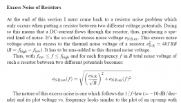
Excess noise of resistors:
Attachments
What about the grid bias current for a vacuum tube in a quality condenser microphone? What about increasing the value of the resistor to over 50 meg ohm in order to lower the self noise of the microphone capsule resistor combination. I use 1 G ohm minimum, myself.
Of course, there is leakage current, and DC offset too! But, quieter performance with a quality resistor, because of its higher value AND its low EXCESS NOISE. I have been using 1-10G ohms for the last 37 years, and even got B&K to use them in their 2619 mike preamp. I will give you technical references through JAES if you need it, for the calculations.
Mosfets are very, very noisy. No hope, yet for them.
So what do you 7 the design team use in the Constellation Audio poer amps:
Quote from Constellation website:
"The Hercules' balanced bridged design delivers a perfect balance between the positive and negative halves of an audio signal. Most balanced amplifiers use N-type output transistors for the positive half of the circuit and P-type transistors for the negative half, which produces an imbalance between the two halves of the signal. We build the Hercules by combining two matched single-ended amplifiers using only N-type output transistors. Because the Hercules uses only one type of output device, every element of the musical signal passes through exactly the same circuit components-and the musicality of the single-ended design is maintained."
Yes, PMA, we have stuff written by marketing people. However, the power amps are based on a transformerless hybrid vacuum tube power amp design first shown to me 40 years ago by Bascom King, the designer of the Hercules power amp, now using mos fets on the driver and output stage. I am pretty sure the input stage uses 2SK170 jfets.
Bascom King has always been a believer in same 'sex' output devices. He was using quasi-complementary output transistor stages, back in 1971 or so, in a Marantz design that he did while there, when complementary output transistors were available and used in other Marantz amps.
For the record PMA, I use 1G ohm resistors or more with jfets. BUT with a SERVO, it might be possible to raise the input resistor on a vacuum tube based condenser microphone input, in order to lower the self noise, BUT there might be a real DC voltage drop, maybe 10V or so. THEN excess noise would be VERY important. Therefore, it is a matter of design application whether excess noise is important.
Even in 1970 or so, B&K used metal film resistors for their hi value input resistors (200 Meg ohms, initially, for the 2619 microphone preamp.
What about the grid bias current for a vacuum tube in a quality condenser microphone? What about increasing the value of the resistor to over 50 meg ohm in order to lower the self noise of the microphone capsule resistor combination. I use 1 G ohm minimum, myself.
That's not my application. I use 5G myself for that. Even at 5G the dominant noise is the RC of the bias resistor and capsule capacitance (20dB/decade) while the excess noise (if it existed) would be 10dB/decade. Even another reason that it does not matter.
Well, since I don't know your application, perhaps it doesn't matter.
There are several applications where it might matter in my audio designs, and perhaps others here, but maybe it is better to get back into a more typical resistance range.
Now, IF you used a 5G resistor, then the typical bias current of a typical lowish capacity jfet might be 1nA, IF you put any significant voltage across it, and kept the operating current 5ma or so. This would drop 5 volts across the resistor. Would this be important? If it would be, then it would eliminate using a simple source follower, unless you both cascoded, and output buffered it, to lower the input current.
On the other end of the scale p.172 Fig. 9-1 of M&F shows the increase of excess noise across a 10K resistor with an NI of 0 dB and 10V DC across it. The curve tends to get worse than ideal below 3KHz or so. When is this important? Perhaps with vacuum tube plate resistors and some input resistors biased with DC which often happens with single power supply operation. Still, I must agree with Scott, that many newer ways of circuit design have taken DC from the most important noise contributing resistors, although I might note that my second stage biasing and servo resistors have about 15v DC across them and it might be a potential noise contribution. It certainly would make the actual noise greater than the nominal resistor value and therefore a potential problem. However, I already use pretty good resistors, but someone trying to copy the circuit might use much cheaper ones and get into trouble. Interesting, I never had to think about that, because I stopped using high NI resistors, many decades ago.
Now, IF you used a 5G resistor, then the typical bias current of a typical lowish capacity jfet might be 1nA, IF you put any significant voltage across it, and kept the operating current 5ma or so. This would drop 5 volts across the resistor. Would this be important? If it would be, then it would eliminate using a simple source follower, unless you both cascoded, and output buffered it, to lower the input current.
That FETgoes in the trash. I've never seen an SK170 over 2-5pA. I've built 5 mic projects now and never had more than 20mV across the resistor.
This reminds me a project of measuring atmospheric discharges near to high voltage power line. Capacitive sensor - plate on rod. Very high input resistance, fast charge amplifier. The small problem was necessary protection against impulse breakdown ..... but it was solved successfully.
- Status
- Not open for further replies.
- Home
- Member Areas
- The Lounge
- John Curl's Blowtorch preamplifier part II