John,
If you truly wanted to do a 3D printed board that has been done for years. it just cost a lot more than a flat FR4 board is going to cost to have a contoured board. I made some laminate with glass/ polyurethane in the past. I wonder what the dielectric values would be on that material. I don't think I know anyone else who has done that. Where there is a will there is a way. It wouldn't be all that hard to make contoured boards if that was really worth it for some reason.
Just use a flexi-rigid, the problem with an air dielectric is gravity, you have to keep the copper apart, it would be rather hard to do!
Personally I would rather go for a well engineered design, rather than one that uses fancy parts and materials just because they fulfil some audiophile fantasies.
To me, wiring, shielding and grounding topology of almost all commercial audio amplifiers is wrong.
Amen. (From a guy who works in RF.)
...the problem with an air dielectric is gravity, you have to keep the copper apart, it would be rather hard to do!
It might be interesting to 3-d print the copper itself, without a 'board'. Challenging to design, maybe pointless, but sort of fun to think about, now that the printing technology is starting to get closer.
How do you suspend the copper tracks in mid air, what holds it all together...And if you use thick copper to keep things rigid (you would need the equivalent of at least 20oz copper) then you would have to use a blowtorch to solder it...
Of course this should not be a problem if we use esoteric audiophile physics🙂
as PMA myself and others have said, getting the layout correct is more important than worrying about using fancy PCB materials...
Of course this should not be a problem if we use esoteric audiophile physics🙂
as PMA myself and others have said, getting the layout correct is more important than worrying about using fancy PCB materials...
Marci,
I wonder if anyone actually uses the flexible boards where they are actually flexed in normal use and not just for packaging in strange configurations? I suspect the copper traces would work harden due to the flexing and then crack the traces but that is just a guess on my part. I agree using a material just because it sounds exotic doesn't necessarily give any improvements besides marketing bragging rights. For that matter why not make the boards out of carbon fiber and use that to augment a ground plane. you could use alternating layers of glass and carbon fabric for multi-layer appications? FR4 made great material for a stiffener in composites construction when you could use it.
I wonder if anyone actually uses the flexible boards where they are actually flexed in normal use and not just for packaging in strange configurations? I suspect the copper traces would work harden due to the flexing and then crack the traces but that is just a guess on my part. I agree using a material just because it sounds exotic doesn't necessarily give any improvements besides marketing bragging rights. For that matter why not make the boards out of carbon fiber and use that to augment a ground plane. you could use alternating layers of glass and carbon fabric for multi-layer appications? FR4 made great material for a stiffener in composites construction when you could use it.
Many ink-jet printers have a flexi on the print head carriage, and they go backwards and forwards millions of times. Avoid all stress points.
You know, I have learned a lot about circuit board execution and material in the last week due to this thread. I have been sitting on my duff for years, not really thinking about it, because it is not what I am in charge of. When my past decisions were challenged, I took a second look at Teflon and Polyimide, as well as FR-4.
This is what I have found.
My earlier choices were OK for the time they were selected. In fact, reinforced Teflon is still a good 'nearly ideal' material for an all-out approach.
Polyimide is not necessary so much today, and it does have some potential drawbacks.
FR-4 comes in MANY configurations and the best constructions are pretty good, at least for low cost hi end, like Parasound. It would appear that FR408 would be practical and pretty good. Other FR-4? Who knows?
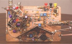
The 'birdcage' layout was first demonstrated by Jean Hiraga, and I bought an example from him in 1978. It wasn't terribly practical, but it was a step in the right direction.
This is what I have found.
My earlier choices were OK for the time they were selected. In fact, reinforced Teflon is still a good 'nearly ideal' material for an all-out approach.
Polyimide is not necessary so much today, and it does have some potential drawbacks.
FR-4 comes in MANY configurations and the best constructions are pretty good, at least for low cost hi end, like Parasound. It would appear that FR408 would be practical and pretty good. Other FR-4? Who knows?
The 'birdcage' layout was first demonstrated by Jean Hiraga, and I bought an example from him in 1978. It wasn't terribly practical, but it was a step in the right direction.
There are different types of flexi boards, I am rather chilled at the moment, drinking beer, listening to music and editing photos, so cant think🙂 but this is a good book and quite comprehensive, the different, page 56 should be of interest and get the copper grain diode effect debate going!
Flexible Circuit Technology, Fourth Edition by Joseph Fjelstad :: Home
Night🙂
Flexible Circuit Technology, Fourth Edition by Joseph Fjelstad :: Home
Night🙂
I do have to agree with you John regarding a lot of FR4 20-30 years ago, it was sometimes lacking. The biggest problem I had was outgassing of PTH holes causing solder voids and literally eruptions of solder on the side of solder joints, plus many other problems that you just don't see today. Now electronics are reliable (tin whiskers of cause will bite, thanks all those that supported removing lead from solder).
Attachments
One of the trite sounding truths about audio reproduction is that "everything matters", and it's a fascinating journey exploring all the branches of this ... IME this never ends; typically the more "transparent" and revealing the system becomes, the more one becomes aware that a subtle variation somewhere has an audible impact - decisions have to be made as to which variation is more "correct", and then the convoy can move on ...You know, I have learned a lot about circuit board execution and material in the last week due to this thread
Fear not to try
😉
George
That looks like something by the great Jim Williams.
Here's an ohm meter I nested. 100% analogue with auto-ranging. Selects a range within 60mS, so it's as quick as a high-end digital multimeter and actually usable. Accurate to within the width of the meter needle. In a nice box and on the bench, gets used all the time. Great for fault-finding.
imgur: the simple image sharer
imgur: the simple image sharer
imgur: the simple image sharer
imgur: the simple image sharer
imgur: the simple image sharer
imgur: the simple image sharer
imgur: the simple image sharer
Because why not 🙂
Attachments
Last edited:
Looks like a Jim Williams (RIP) piece.
(He also did some pure 'Art' stuff - I think it was published in one of the Linear Tech apps books)
(He also did some pure 'Art' stuff - I think it was published in one of the Linear Tech apps books)
EMC!
Of course.
These debates with amateurs are close to useless. I am always surprised what they are able to create.
Just read the last three pages.
Why not make PCB's out of cotton t-shirts?
Would be cheaper than Teflon and probably perform just as good.
Why not make PCB's out of cotton t-shirts?
Would be cheaper than Teflon and probably perform just as good.
Last edited:
Of course.
These debates with amateurs are close to useless. I am always surprised what they are able to create.
Some get lucky, others listen to what pros say and keep it in mind. Which is not to say that the pros sometimes do not succumb to fashon, or overdo it. Still, I feel it's better to overdo it in the right direction.
- Status
- Not open for further replies.
- Home
- Member Areas
- The Lounge
- John Curl's Blowtorch preamplifier part II