Thank you for the measurements.
> Sizes does matter .....
I wonder if it has anything to do with the internal resistance.
Patrick
I am fairly sure it does. Also, as the battery is discharged (a question I asked earlier) the battery Z increases.... thus, so would the noise.
THx-RNMarsh
One trick is to mix down RF noise to DC, Quantec sold a box that did that. I have one.
EDIT - Model 420, can't find a free schematic.
I have 2 of those. I thought i had a manual but I don't see it.
Assuming the RF noise level is high enough to swamp out 1/f issues in the mixer and the circuit is DC coupled it should be pretty linear to DC.
Gerhard:
RE: sound cards- if the signal level is high enough over the internal issues of the sound card then its errors should not be significant. Most audio ADC's have a switchable high pass function that would be enabled. It could cause problems with very low frequencies. Some sound cards are pretty good and would not be a big roadblock. If you need to go higher performance its not difficult to get a demo board from TI or AKM that is easily modified for your purposes and bring it in via SPDIF. The AKD5394A board uses through hole parts for the analog into the ADC. As a demo board you can easily switch off the high pass filter. You could even DC couple it. Its measurements so a lot of the audiophile issues are irrelevant.
If the end goal is measuring oscillators there is a lot of info on doing that. The phase noise floor of the 89441A at -112 dBC at 1 KHz is the real limitation and you will blow past that pretty quickly unless you are measuring at 1 GHz+.
I cooked up this simple supply for crystal oscillators for just this reason: http://www.diyaudio.com/forums/digi...sb-interface-audio-widget-92.html#post2863700
One trick is to mix down RF noise to DC, Quantec sold a box that did that. I have one.
EDIT - Model 420, can't find a free schematic.
Yeah! how could I forget this! Mixing dirt onto an otherwise perfectly good carrier
is somehow against my dearest habits.
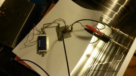
But, no need to buy from Quantec: In the junk box was an Avantek wideband amplifier,
54 dB from 10 MHz to 1000 MHz. Given that Avantek has been bought by HP, it must
really be prehistoric. I screwed an 50 Ohm SMA load on its input.
The junk box also had a test board with a MCL TUF-1H ring mixer that
was used as a phase discriminator recently.
The LO port of the mixer got +10dBm / 100 MHz from a R&S SMPD signal generator.
The IF port got a 120pF/???uH/120pF low pass to protect the AF preamp from
too much RF.
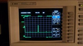
Then came my usual 20*ADA4898 AF preamp with 40 dB of gain only, then it went
into the Agilent 89441A. With enough level to to swamp the built-in 1/f noise:
It is as flat as can be, even on this DC to 100 Hz FFT.
OK, you cannot escape the mains spur ( which has 30 Hz sidebands, funny...)
When I switch off the 100 MHz generator, I see the FFT analyzer's 1/f noise
somewhere in the cellar.
What is interesting is that the 230 or so averages for 0..100 Hz took _much_ longer
than the 200 averages for 0.1 to 1Hz when executed under control of my program.
Attachments
Last edited:
What is interesting is that the 230 or so averages for 0..100 Hz took _much_ longer
than the 200 averages for 0.1 to 1Hz when executed under control of my program.
Should you try the same test with your program? Perhaps the math is different? Or more likely its a demonstration that an 8502 is no longer a competitive processor. I believe the next generation moved to XP running on a small motherboard.
RE: sound cards- if the signal level is high enough over the internal issues of the sound card then its errors should not be significant. Most audio ADC's have a switchable high pass function that would be enabled. It could cause problems with very low frequencies. Some sound cards are pretty good and would not be a big roadblock. If you need to go higher performance its not difficult to get a demo board from TI or AKM that is easily modified for your purposes and bring it in via SPDIF. The AKD5394A board uses through hole parts for the analog into the ADC. As a demo board you can easily switch off the high pass filter. You could even DC couple it. Its measurements so a lot of the audiophile issues are irrelevant.
No. Definitely, No! 50 KHz, or even 100 KHz is not enough, and 20 Hz on the
low side is also not enough. No more sound card drivers for x-Linux and/or y-windows,
I had it and I have enough of it. No more any music I happen to hear on the
laptop in my measurements.
If the end goal is measuring oscillators there is a lot of info on doing that. The phase noise floor of the 89441A at -112 dBC at 1 KHz is the real limitation and you will blow past that pretty quickly unless you are measuring at 1 GHz+.
I cooked up this simple supply for crystal oscillators for just this reason: http://www.diyaudio.com/forums/digi...sb-interface-audio-widget-92.html#post2863700
I once build the Jung reference and regulator and a lot of other stuff and I'd like to
characterize it. When the setup is automated, that will will be easy, also for RNMarsh's
empty batteries. 😉
I have an E5052B a few roomdoors away at work, and it is easy to get plots to -180 dBc
from it. As much as the E5052 is concerned. The test objects, that's a different story.
It has an ultraclean control- and a supply voltage that I could use. In March I also
had a R&S FSUP on the same table, and they disagreed by some dB. There is also
a Timepod, and that is what I really like. Cheap & reasonable.
Attachments

Should you try the same test with your program? Perhaps the math is different? Or more likely its a demonstration that an 8502 is no longer a competitive processor. I believe the next generation moved to XP running on a small motherboard.
It has an 68030 + 68882 for housekeeping, ftp, filesystem, whatever. The numerical
work is done in DSPs & hardware fir filters.
My program does only the setup via TCP/IP and the output formatting. There are small
differences such as FFT 0..100 Hz vs. 1.0..10, 10..100Hz, use of overlapping FFTs under
program control to speed things up... Still experimenting.
Maybe we should have started a different thread. Looks like we have scared away
the lounge inhabitants.
Unfortunately that construction is only meaningful in larger quantities. The MOQ to justify that stuff is usually larger than the commercial life of a high end audio product. If you need to spin the board a few times its even more painful. Laser drilled blind vias in pad are very much state of the art and only the most premium board shops can even do that stuff. It makes sense for a million piece cell phone order.
With the tiny resistors tempco and modulation with signal will be a much bigger issue,there isn't much thermal mass to absorb changes.
I am adapting to surface mount. I acquired a good stereo microscope and a handful of other specialized tools. I can deal with 0201's if necessary but not because I want to. Coming from through hole 0604 looks tiny. In the world of SMT they are gigantic.
With the availability of Chinese manufacturing and the ever reducing size of components (0.5mm pitch BGAs require microvia in pad, no other way of routing them) we do more and more via in pad and HDI designs, and cost differences are not that bad, when you consider a BGA board can easily hit 3000+ drill hits (0.3mm drill!), a long time for mechanical drilling a 1.6mm laminate. Do a 2-6-2 HDI board and you can drop your drilled vias by a third and even with the sequential build up it still takes less production time.
Obviously not the technology for audio amps, but the digital side of things its perfect, the control it allows you for separation and control of different signals is incredible, you can totally isolate analogue and digital by layers as well as areas, balanced signalling etc, 10 layers 3-4-3 stacked microvias, proper top end digital. Done some similar things but not for domestic audio, it opens up a whole new world. That why we can cram RF, audio, processor and memory with USB into just about every hand held device these days. Over the next few years it will grow, as has happened with component size reduction, certain areas of IC development it is driven by the portable, hand help mobile phone companies that fund the research either directly or by the chance of large sales of components.
Of course it gets silly...
JIESHINE - Has introduced the 01005 chip resistors of the world's smallest electronic components
🙂
Maybe we should have started a different thread. Looks like we have scared away
the lounge inhabitants.
Some of us operate on the principle that listening is a good alternative to talking unless you have something to contribute ... 😎
Jan
Some of us operate on the principle that listening is a good alternative to talking unless you have something to contribute ... 😎
Jan
+1
To lighten my laptop, I deleted several files. To my surprise, none of my scales were able to show any reduction. Because I know my process worked, I hope some day that science will be able to measure weight more accurately.
Superb!
It has an 68030 + 68882 for housekeeping, ftp, filesystem, whatever. The numerical
work is done in DSPs & hardware fir filters.
My program does only the setup via TCP/IP and the output formatting. There are small
differences such as FFT 0..100 Hz vs. 1.0..10, 10..100Hz, use of overlapping FFTs under
program control to speed things up... Still experimenting.
Maybe we should have started a different thread. Looks like we have scared away
the lounge inhabitants.
Judging from the responses there is an audience that is listening. I guess this is some real engineering for once. Maybe we should go elsewhere. We shouldn't clutter up the pontifications with facts should we?
I was close to buying a Timepod but then Symmetricon bought the project and the price doubled. I could not really justify the price then and definitely not now. And I think there is a valid question as to whether a lower phase noise/jitter will actually produce lower noise/distortion on a DAC when you go below the mathematical limit for the resolution. Can the Timepod be persuaded to make this noise measurement? It has two very good ADC's and the cross correlation stuff in it. John Miles is quite approachable.
Since you have access to all the expensive toys have you verified that they give the same results? And at -180 dBC verification must be difficult.
For the power supply noise, you are looking both below 10 Hz and above 100 KHz, a much broader band than I was interested in. The coupling caps will be an issue. Jim Williams highlighted it in his note and referred to an almost unobtainable wet slug tantalum cap he used. Have you compared caps in the DC coupling location?
To lighten my laptop, I deleted several files. To my surprise, none of my scales were able to show any reduction. Because I know my process worked, I hope some day that science will be able to measure weight more accurately.
You know the orientation of the magnetic domains on the disk are vertical on current disk drives so its weight will be less if oriented properly with the earths magnetic field. In the older drives with lateral recording in a circle the fields would cancel. Edison was right to use vertical recording. Berliner's lateral recording used too much space. Only took 100 years to figure that out. You should be able to measure weight change with an electron force microscope.
To lighten my laptop, I deleted several files. To my surprise, none of my scales were able to show any reduction. Because I know my process worked, I hope some day that science will be able to measure weight more accurately.
Information processing takes energy and dissipates it thermally, so when running your laptop on a battery, you further deplete
the stored energy by deleting files. Since thermal energy has mass, the mass (and weight) is indeed less.
For the power supply noise, you are looking both below 10 Hz and above 100 KHz, a much broader band than I was interested in. The coupling caps will be an issue. Jim Williams highlighted it in his note and referred to an almost unobtainable wet slug tantalum cap he used.
Wet slugs are an interesting study as coupling caps. They are too rich for your average audiophiles pocket book, with lots of bad press when applied by idiots. Unfortunately easily available, small quantity, values aren't properly suited to the most benificial audio applications but they are an interesting read. Many years of playing invested here.
Mike
Last edited:
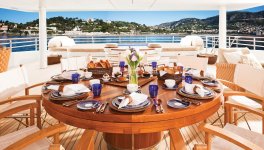
Thought some here might appreciate a very nice example of modern engineering.
Making the Fletcher Capstan Table - YouTube
🙂
Making the Fletcher Capstan Table - YouTube
🙂
Thought some here might appreciate a very nice example of modern engineering.
Making the Fletcher Capstan Table - YouTube
most parts custom made
retail price $150,000
Making the Fletcher Capstan Table - YouTube
most parts custom made
retail price $150,000
very nice
Half the superyachts over 165ft have such tables nowadays.
Example of a 205ft Icon that has two DB Fletcher's, a kapstan on the bridge deck, the multi-game table in a dedicated room on the upper deck.
All yours, if you make an offer in the vicinity of $77.5M.

(Jen Wartena , managing director of Icon, is an old class mate, nice bloke)
Attachments

- Status
- Not open for further replies.
- Home
- Member Areas
- The Lounge
- John Curl's Blowtorch preamplifier part II