When the output voltage exceeded about 20V pk-pk, into a dummy load, the amp board would 'sing' and as I changed the frequency, the tone would change and then if I changed too much, disappear.
The culprit was a 1nF 1kV leaded ceramic capacitor used in the damper network betwen my driver and the output stage devices.
Piezoelectric acoustic transducer 😀😀
propagate from a mechanical source
Output devices have mica & goop between them and the heatsink.
There'd have to be quite a big hammer between die and base plate of the device to generate enough excitation force to hit the eigenvalue of a heatsink.
From driver cone to heatsink is airborne excitation.
I was thinking more about electrostriction with an attached soundboard.
Look Ma, walking Willies !
http://upload.wikimedia.org/wikiped...bimorph.gif/800px-Piezomotor_type_bimorph.gif
It would seem that all airborne excitations have to propagate from a mechanical source originally?
My thoughts , if not from outputs , vas? Caps ? Output inductor could be a source ...
Thanks for your ideas on the mystery transducer... I think it is important to consider whether the tone is frequency doubled or not, as this would narrow down the possible sources.
Both of our solutions do this. My solution presents a common-mode inductive reactance and so does yours. This is in series with the ground fault. The effect of the opamp is mainly to magnify the inductive reactance by 200 times in my simulation.
This circuit cannot zero the ground current in practice, and if it tries it will clip trying to drive the choke near DC. If there is a DC ground fault the current will still flow, for both our circuits.
A 3-coil CM choke (or two normal CM chokes) can do the same thing, and that is really what you'd have with differential cables going through the 2 toroids; the opamp only magnifies the behavior. My solution is just convenient because you can pull CM chokes out of a lot of power supplies. Your solution however could allow us to get more inductive reactance per coil size.
That moves the input to compensate for the ground.
Both of our solutions do this. My solution presents a common-mode inductive reactance and so does yours. This is in series with the ground fault. The effect of the opamp is mainly to magnify the inductive reactance by 200 times in my simulation.
The active circuit tries to zero the ground current.
This circuit cannot zero the ground current in practice, and if it tries it will clip trying to drive the choke near DC. If there is a DC ground fault the current will still flow, for both our circuits.
If the ground current is attacking other parts of the equipment, zeroing it is better. For example, loop coupling at the output stage of the source, ground path to circuit coupling in the amplifier. Whitlock only considers IR drop in his presentations, so not removing the current may not remove the problem, and two channel inputs may be worse. The active solution can be applied to multiple channels as well as differential inputs, eliminating the pin 1 problem.
jn
A 3-coil CM choke (or two normal CM chokes) can do the same thing, and that is really what you'd have with differential cables going through the 2 toroids; the opamp only magnifies the behavior. My solution is just convenient because you can pull CM chokes out of a lot of power supplies. Your solution however could allow us to get more inductive reactance per coil size.
Is this excitation one of the reasons why amplfiers sound different when placed on stands , floor , etc ... ?
Output devices have mica & goop between them and the heatsink.
There'd have to be quite a big hammer between die and base plate of the device to generate enough excitation force to hit the eigenvalue of a heatsink.
From driver cone to heatsink is airborne excitation.
Jacco, my experience of this was with a dummy load - no speaker driver.
I never thought much about this, it's something I noticed agian and again over decades of fiddling with power amps.
I am very surprised about the reactions - does anyone spend time at a test bench anymore??
Jan
I always thought heatsink 'singing' was perfectly normal (on the test bench into dummy load).
Some amplifiers have rubber bungs fitted between the fins to prevent the ringing..motorcycle engines too !.
This ringing varies with level, and intensifies significantly at onset of clipping with music signal, or test tone.
I have lifted such heatsinks to isolate them from chassis borne vibrations/excitations, and the effect remained undiminished.
Dan.
Output devices have mica & goop between them and the heatsink.
There'd have to be quite a big hammer between die and base plate of the device to generate enough excitation force to hit the eigenvalue of a heatsink.
From driver cone to heatsink is airborne excitation.
They should have the thinnest possible amount especially of the 'goop', and if the mica is not required then is 'goop' only, but the tab should be securely fastened to the heat sink otherwise thermal transfer is limited.
Why would DC cause active clip? The input choke doesn't transfer it. edit: a clip indicator would be great as well...This circuit cannot zero the ground current in practice, and if it tries it will clip trying to drive the choke near DC. If there is a DC ground fault the current will still flow, for both our circuits.
First, it's not my solution, credit is deserved by the authors.A 3-coil CM choke (or two normal CM chokes) can do the same thing, and that is really what you'd have with differential cables going through the 2 toroids; the opamp only magnifies the behavior. My solution is just convenient because you can pull CM chokes out of a lot of power supplies. Your solution however could allow us to get more inductive reactance per coil size.
I prefer the smaller choke as a ground fault through the input shield (remember code requires bonding of all conductive surfaces that may become energized) and a large choke may provide too much reactance to clear a breaker. Very small ones should saturate quickly and drop reactance, clearing the breaker. Care of shield ampacity is required of course.
Cheers, john
with a dummy load
But are it the output stage devices which excitate the heatsink resonance, or e.g. the power transformer under load ?
I've soft-mounted/suspended everything over the last decades of amp fiddling ; transformer, boards, heatsink, fans.
Also a sport to find dampening hardware for pennies, which can be used or modified for use.
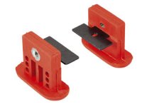
Neoprene vibration grommets cost less than a dime each (though Digikey charges $1). One on each side of a mounting hole means ~3 quarters to soft-mount a board, and no need to drill larger holes.
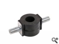
Less than 50 cents each (got a few hundred of these
 ) =>
) =>Attachments
Jacco, my experience of this was with a dummy load - no speaker driver.
I never thought much about this, it's something I noticed agian and again over decades of fiddling with power amps.
I am very surprised about the reactions - does anyone spend time at a test bench anymore??
Jan
Same here , on the bench with dummy load ...
Jacco, do you have the Part Nr.'s of the red ones? Thanks!Neoprene vibration grommets cost less than a dime each (though Digikey charges $1). One on each side of a mounting hole means ~3 quarters to soft-mount a board, and no need to drill larger holes.
Less than 50 cents each (got a few hundred of these
Anything mounted on a board should be solidly mounted to the board, large caps benefit from a blob of silicone (as do other large components), then mount the board using AV mounts.
acoustic damping steel is also fun to play with, an A4 sheet or 3 can go a long way.
Your SEO optimized title
acoustic damping steel is also fun to play with, an A4 sheet or 3 can go a long way.
Your SEO optimized title
I always test my SMPS into a dummy load at various powers and have to report, other than the cap episode, I've never had a singing issue, and especially with heatsinks.
Baffled. What's the physical mechanism? (BTW I have heard magneto restriction in SMPS transformers)
Baffled. What's the physical mechanism? (BTW I have heard magneto restriction in SMPS transformers)
But are it the output stage devices which excitate the heatsink resonance, or e.g. the power transformer under load ?
I always thought it is the output devices because I often test with just a heatsing and amp board with remote regulated power supply.
You need to draw appreciable load to make it audible though.
Something to pick up and verify when I have a chance.
Jan
Don't see any. Did you buy their whole stock? 😀NOS, Pollin in Germany, Nr 40681
I always test my SMPS into a dummy load at various powers and have to report, other than the cap episode, I've never had a singing issue, and especially with heatsinks.
Baffled. What's the physical mechanism? (BTW I have heard magneto restriction in SMPS transformers)
Thats Because you are not using a real supply .... 🙂
- Status
- Not open for further replies.
- Home
- Member Areas
- The Lounge
- John Curl's Blowtorch preamplifier part II