Vacuum valves have enough heat lost through radiation that an external flat black metal shield (by nature with more area than their anodes) increases valve working life. Presumably by better cooling. I guess you have to be pretty hot to start with for it to matter. Or so the girls tell me.
Thanks,
Chris
Thanks,
Chris
Another remark:
Again according to Hofer, the benefits of the switchers include, finally and for the first time, no detectable line-frequency-related spurs in the DFT. Although some aspects of the new instruments, according to some friends' evaluations, are not quite as good as the system two, the removal of the toroid and its inevitable magnetic field radiation apparently accounts for the absence of the spurs.
One of the big challenges with switchers is the changing frequency or duration to get the regulation. This generates subharmonics that can cause problems. Good common mode chokes that work to RF and up plus good magnetic isolation would be critical for success. Also capacitive coupling between input and output of the supply could compromise all the other work.
And then no audiophile worth his power cable fetish would let an evil switcher into his system.
I am repeating a point I made earlier- a really good, available switcher for low level stuff (25W-50W) would be really interesting.
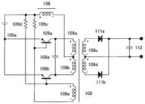
Fidelix Serenity Power Suppy its in Japanese
US7272019
To provide a switching power supply apparatus which can achieve the followings simultaneously in high levels: the voltage waveform capable of reducing switching noise to the least is in a sine-waveform; capable of providing an output of stable voltage without a control, and a simple response; and capable of corresponding to instantaneous peak current without having saturation of the core.
It relates to an improvement of a resonance-type Royer converter with less switching noise as a base, which is directed to be used for audio equipment. A second inductor is inserted to the primary side inductor between a rectifier circuit and a smoothing means, which is coupled to the primary-side inductor in a same magnetic circuit in a direction of canceling a DC magnetic flux.; Moreover, timing of the next cycle is determined by applying a center tap voltage of a transformer to a synchronous signal input terminal of a control IC. Thereby, a self-excited oscillating action is actually stabled. With this, high demands for use in audios can be satisfied simultaneously.
Attachments
I had never thought about it but a physicist freind pointed out that no concentration of solar rays can make a temperature more than the surface of the sun on any object.
To get a higher temperature would violate the second law. Heat is not just calories, but higher temperatures also have higher information content.
The telecom market has been using switchers in the 500 to 6 kw range for 25 years now. They've gone from --88-90% efficient, .7 power factor, <35% current distortion, 50 lbs, operating at 20khz, and the size of a microwave for 3 kw to now being 96 % efficient, .99 pf, <5% input distortion, 4 lbs, 150khz single stage designs, and the size of a pocket novel. Early units rarely meet radiated and conducted EMI claims, the latest ones are pretty small in physical size helping concentrate the emi generating/radiating/filtering. Transient response is about 1 ms recovery for a 90% step change with a 2% max deviation with 2 Mv weighted ripple with 100 Mv peak to peak rf which additional common mode choke filtering will improve. Cost and noise has kept good switchers out of power amps and preamps - Europeans are ahead of the rest of us in implementing them because of power conservation efforts there focused on power factor and efficiency. As manufacturers refine or adapt the designs to suit audio we'll see more of them as they can actually perform/sound better than increasing the bulk filter capacitors in a linear supply - they approach the output regulation of a switcher.
The main road block to wider implementation in the audio industry is the same one affecting jfets - not enough volume to justify audio industry specific components and cost (which is improving as size shrinks and efficiency increases). Audio manufacturers are forced to adapt commercial designs or try to build their own (although given the degree of expertise required to achieve good results increasingly less likely - the better units use software controlled 64/128 pin u controllers to manage switching functions for best performance with single stage PF corrected 96% units - the simpler PWM control chips of earlier years first used 1 stage at lower frequencies to reach 90% efficiency, then needed 2 stages, one optimized for input power factor, the second stage converter doing DC/DC conversion and still resulting in 90% efficiency. The difference between 90 and 96% efficiency doesn't sound like much until you calculate heat losses and heat sinks - 96 % is only 40% the losses of a 90 % efficient unit.
The main road block to wider implementation in the audio industry is the same one affecting jfets - not enough volume to justify audio industry specific components and cost (which is improving as size shrinks and efficiency increases). Audio manufacturers are forced to adapt commercial designs or try to build their own (although given the degree of expertise required to achieve good results increasingly less likely - the better units use software controlled 64/128 pin u controllers to manage switching functions for best performance with single stage PF corrected 96% units - the simpler PWM control chips of earlier years first used 1 stage at lower frequencies to reach 90% efficiency, then needed 2 stages, one optimized for input power factor, the second stage converter doing DC/DC conversion and still resulting in 90% efficiency. The difference between 90 and 96% efficiency doesn't sound like much until you calculate heat losses and heat sinks - 96 % is only 40% the losses of a 90 % efficient unit.
Last edited:
I was wondering what the temperature of the sun had to do with audio, but now I realize if it didn't have a temperature neither would we.
Clearly the stripe pattern is a stealth coating..Doesn't explain why Zebra's aren't on the list.
Thanks
-Antonio
jn
Most likely, in infrared, zebra's are all black.
Dead ones maybe.
edit: Actually, I believe for some thermal control of space craft instruments a combination of white and black paints are used to achieve the desired average absorption.
Thanks
-Antonio
Last edited:
Doesn't matter. The power density doesn't produce a very large temperature gradient through the paint. What, a kilowatt through a square meter in a radiator? Power semi's do a kilowatt per cm squared, or 10 megawatts per meter squared.
I always knew that flat black was best...matte black has a coefficient of 1..
Hmmm..I halved my heating bill with a can of non expanding foam from home depot and outlet foam insulators. Sometimes it's difficult attributing a change to one specific thing, specially if you do more than one thing different.
Hey, on those breakers....weren't they both mag and heat? Seems to me that all breakers have two regimes, one thermal and the mag for bolted fault.
Oh, big time. I was just gonna paste up to black paint, but said to myself...yo, stupid...it's just ones and zeros, put it all up...
Honestly, some of the numbers surprised me..I thought bare alum was better than that.
jn
Interesting it seems none of you have seen what a 100 year old steam radiator looks like.
Back then they were almost always placed in recesses underneath windows. As they ran dry steam, covers were mandatory. Now what the thermal loss is from the 20 or so layers of paint on the front I have no idea. But think of flaking paint that keeps getting painted over including air bubbles and whatever dust and dirt was there.
I find it believable that after a renovation they saw a 20% cost reduction in heating. Of course they probably patched any holes at the same time.
Now for fun I ran the heatsink demo program for the same example with and without radiation. Results are attached.
Attachments

In
Now for fun I ran the heatsink demo program for the same example with and without radiation. Results are attached.
If the program uses radiation from interior verticle surfaces it is wrong. Did you ever use one of those aluminized mylar emergency blankets, think image source of you and mirror (at infra-red).
My first house had steam, free standing radiators, no covers, painted with some horrible putty colored lead paint.
Last edited:
The telecom market has been using switchers in the 500 to 6 kw range for 25 years now. They've gone from --88-90% efficient, .7 power factor, <35% current distortion, 50 lbs, operating at 20khz, and the size of a microwave for 3 kw to now being 96 % efficient, .99 pf, <5% input distortion, 4 lbs, 150khz single stage designs, and the size of a pocket novel. Early units rarely meet radiated and conducted EMI claims, the latest ones are pretty small in physical size helping concentrate the emi generating/radiating/filtering. Transient response is about 1 ms recovery for a 90% step change with a 2% max deviation with 2 Mv weighted ripple with 100 Mv peak to peak rf which additional common mode choke filtering will improve. Cost and noise has kept good switchers out of power amps and preamps - Europeans are ahead of the rest of us in implementing them because of power conservation efforts there focused on power factor and efficiency. As manufacturers refine or adapt the designs to suit audio we'll see more of them as they can actually perform/sound better than increasing the bulk filter capacitors in a linear supply - they approach the output regulation of a switcher.
The main road block to wider implementation in the audio industry is the same one affecting jfets - not enough volume to justify audio industry specific components and cost (which is improving as size shrinks and efficiency increases). Audio manufacturers are forced to adapt commercial designs or try to build their own (although given the degree of expertise required to achieve good results increasingly less likely - the better units use software controlled 64/128 pin u controllers to manage switching functions for best performance with single stage PF corrected 96% units - the simpler PWM control chips of earlier years first used 1 stage at lower frequencies to reach 90% efficiency, then needed 2 stages, one optimized for input power factor, the second stage converter doing DC/DC conversion and still resulting in 90% efficiency. The difference between 90 and 96% efficiency doesn't sound like much until you calculate heat losses and heat sinks - 96 % is only 40% the losses of a 90 % efficient unit.
In the late 1970's I was working with a 56 Volt 500 Amp psu that was about 96-97 % efficient. 3 phase in with offset delta windings and reverse offset delta windings they ended up with a lot of phases to hop between to keep the efficiency up. They did the load testing in a small internal lab with only a small fan!!!
If the program uses radiation from interior verticle surfaces it is wrong. Did you ever use one of those aluminized mylar emergency blankets, think image source of you and mirror (at infra-red).
My first house had steam, free standing radiators, no covers, painted with some horrible putty colored lead paint.
Scott,
I think I confundicated youins. The data was for typical aluminum heatsinks, that is what the program does. I was showing even on a typical heatsink at normal temperatures radiation is an important part of the cooling.
The other issue was steam radiators. In domestic use it would be wet steam (212 degree F) In commercial buildings it would be dry steam (Well above 212.) It would be a bad thing if touching a radiator at home left you with serious burns. In a commercial building you probably couldn't get heat to all 12 floors with wet steam.
ES
Scott,
I think I confundicated youins. The data was for typical aluminum heatsinks, that is what the program does. I was showing even on a typical heatsink at normal temperatures radiation is an important part of the cooling.
ES
Question authority. I'm saying if the thick/thin fins in the figure is turning on/turning off of radiant cooling it is wrong (and maybe they have made a mistake). The faces facing each other do not radiate away from the heat sink.
Question authority. I'm saying if the thick/thin fins in the figure is turning on/turning off of radiant cooling it is wrong (and maybe they have made a mistake). The faces facing each other do not radiate away from the heat sink.
Yes I understood you thought that. It also seems logical.
I really don't want use the argument, the simulations proves otherwise. However it is an accurate program. So the issue becomes how much heat from radiation does the little bit of air between the fins absorb? Or does the program only look at the radiation from the base and not the fins? I don't know what the mechanism is. But the program does work and almost all commercial heatsinks do get turned black.
I know from hooking up resistors to heatsinks there is a large difference before the aluminum is anodized and after, but I haven't recorded the numbers.
Yes I understood you thought that. It also seems logical.
I know from hooking up resistors to heatsinks there is a large difference before the aluminum is anodized and after, but I haven't recorded the numbers.
Every heat sink design manual I have seen states in the case of almost any forced air, radiation can be completely ignored. The difference is not large. Sorry Ed just taped out a big project and I'm in the mood for a good discussion/argument.😀
Jeez Ed my physics text gives blackbody radiation at 100C and emissivity of 1 at 1W/square METER.
Last edited:
I wonder what 'amateurs', you know the majority of people out there, when it comes to audio design, are getting from this heated discussion? If they are typical, I would say that they are getting confused, more than getting a better grasp of the subject.
When I first spoke about power devices, I mentioned that the WAY that you determine the actual useful power dissipation between solid state devices and tubes was DIFFERENT. Significantly different enough to confuse a layman, and even some engineers, perhaps.
This does NOT take a lecture from SY on thermodynamics or from JN on spread angle of the heat distribution. Usually we can control these factors, OR a commercial manufacturer will do it for us, before we buy a commercial heatsink.
What I was TRYING to get at was that the SMALLER effective area that you have to work with for a heat source, the HARDER it is to get the heat out, all else being equal. So when you have smaller and smaller heat sources, it becomes more difficult to get the heat out, so maybe you should start with a larger heat source, if possible, to make your amplifiers.
Primarily I was thinking about the difference between T0-3 (metal or plastic) and T0-220 plastic packages with the SAME die inside.
I wanted to point out that one can be fooled by the POWER RATINGS of power semiconductors, IF you are not somewhat aware of the differences in effective radiating surface area that is defined by the package.
Then secondarily, I wanted to show the differences between commercial power semiconductor insulators that are usually necessary for useful operation.
Finally, I wanted to point out that aluminum is OK, but copper, especially close to the heat source, can be useful, and that there are even better materials, even if they are almost impossible to afford in commercial equipment.
I was not going to design heatsinks here, that is another topic.
I regret not being able to go very far without being sidelined on the subject.
Incorrect. Had seven of them, replaced all with slantfin during a house reno. Heavy suckers, one was 6 feet long.Interesting it seems none of you have seen what a 100 year old steam radiator looks like.
Back then they were almost always placed in recesses underneath windows. As they ran dry steam, covers were mandatory.
Covers??? Yah, right..
Doesn't matter. The power density is not high, so gradient within paint is very small even with air bubbles under flakes.Now what the thermal loss is from the 20 or so layers of paint on the front I have no idea. But think of flaking paint that keeps getting painted over including air bubbles and whatever dust and dirt was there.
The holes are the biggie. Air infiltration/exfiltration is the largest consumer of heating energy in old houses bar none. A 5 dollar can of foam and one rolled up bathroom rug and I reduced my heating cost 50%...after 3 months, they owed me 600 dollars. (The house was on a bill budgeting program, so I was paying for previous owners historical cost.)I find it believable that after a renovation they saw a 20% cost reduction in heating. Of course they probably patched any holes at the same time.
I can't read the results.Now for fun I ran the heatsink demo program for the same example with and without radiation. Results are attached.
How does the program determine which radiation escapes and which is re-absorbed?
Agreed.If the program uses radiation from interior verticle surfaces it is wrong.
You showed only what the program did. I can't tell if it is accurate.Scott,
I think I confundicated youins. The data was for typical aluminum heatsinks, that is what the program does. I was showing even on a typical heatsink at normal temperatures radiation is an important part of the cooling.
Ah, covers...you hadn't specified commercial.In commercial buildings it would be dry steam (Well above 212.)
Again, agreed.Question authority. I'm saying if the thick/thin fins in the figure is turning on/turning off of radiant cooling it is wrong (and maybe they have made a mistake). The faces facing each other do not radiate away from the heat sink.
NONE.So the issue becomes how much heat from radiation does the little bit of air between the fins absorb?
Or does the program only look at the radiation from the base and not the fins?
The radiation of the heatsink must be modelled as a 4 sided box. There are ONLY 4 equiv. surfaces emitting. The bottom of the base, the top of the base, the right fin right surface, and the left fin left surface. That's it.
If you keep the same overall size and change the number of fins, and the result changes, the program is wrong.
That is a direct result of anodizing's emissivity compared to bare aluminum. Notice the difference was rather large..I know from hooking up resistors to heatsinks there is a large difference before the aluminum is anodized and after, but I haven't recorded the numbers.
jn
No, many understand.I wonder what 'amateurs', you know the majority of people out there, when it comes to audio design, are getting from this heated discussion? If they are typical, I would say that they are getting confused, more than getting a better grasp of the subject.
For you, it takes even more lecturing...as you still do not understand...I will insert accuracies within your text...This does NOT take a lecture from SY on thermodynamics or from JN on spread angle of the heat distribution.
jnWhat I was TRYING to get at was that the SMALLER effective area that you have to work with for a heat source, the HARDER it is to get the heat out, all else being equal. (correct for the most part) So when you have smaller and smaller heat sources, it becomes more difficult to get the heat out, so maybe you should start with a larger heat source, if possible, to make your amplifiers.
Primarily I was thinking about the difference between T0-3 (metal or plastic) and T0-220 plastic packages with the SAME die inside.
I wanted to point out that one can be fooled by the POWER RATINGS of power semiconductors, IF you are not somewhat aware of the differences in effective radiating surface area that is defined by the package. (big time mistake. Your example of TO-3 and TO-22 are a case in point. The dissipation rating of these devices have NOTHING TO DO with the case size, but on the conduction path. You using the term radiating surface is a whopper of an error. The bigger issue with the TO-220 and TO-3 is the number of holes. TO-220 flanges bend and lose contact if overtorqued. A bridge clamp is best.)
Then secondarily, I wanted to show the differences between commercial power semiconductor insulators that are usually necessary for useful operation.
Finally, I wanted to point out that aluminum is OK, but copper, especially close to the heat source, can be useful, and that there are even better materials, even if they are almost impossible to afford in commercial equipment. (entirely accurate. Better than bulk copper is quite expensive. Heat pipes are not too bad, forced water cooling good, diamond kinda expensive..
I was not going to design heatsinks here, that is another topic. (blame Ed. However, your myth about radiating area for power device packages must be show for what it is...a myth.)
I regret not being able to go very far without being sidelined on the subject.
- Status
- Not open for further replies.
- Home
- Member Areas
- The Lounge
- John Curl's Blowtorch preamplifier part II