Good Idea Bonzai. It will only triple the power supply draw, and 3 times the heat. This original design that I put up was for insertion into the Parasound JC-2 preamp to provide phono input. More heat and more 3 times more current was not recommended.
I think you are going off on a tangent again.
Nope, just correcting your false assumption about my measurements and Jones's. And you may also be incorrect about datasheet methods (confusing ESL with ESR). I haven't looked up any IEC standards.
http://www.epcos.com/web/generator/...__en.pdf;/PDF_GeneralTechnicalInformation.pdf
See Figure 19.
The point remains, whether you care to deal with it or not, a 10,000uF cap has impedance in the milliohms at 3k, 6k, or wherever you decide to move the goalposts. With practical, properly engineered basic regulated supplies (which is not a high hurdle), the noise from the 3k, 6k, or whatever ripple component at the output of a good IC based preamp is lower than -200dBV, deeply buried in the thermal noise of the universe. It doesn't make as much fun for articles or internet postings, but it's nonetheless true.
I'm sure it's fine for what it is, and indeed most MM cartridges have high internal thermal noise. One Ortofon product described as a high-output moving coil managed 80 ohms and 450mH, if memory serves, and wanted to see 47k damping, so it's an example of something that could benefit from low current noise, including the contribution of that termination.Bcarso, your concern is noted, but the emphasis in this design was performance with a large number of phono cartridges, BUT NOT EVERY POSSIBLE CARTRIDGE. It is virtually impossible without significant compromise in op amp loading or extra cost.
There is no 10dB penalty, because the moving magnet cartridges have their own 500 ohms or so DC resistance, so even IF I reduced my 500 ohm feedback resistor to 50 ohms, I would gain only 3dB in the MM gain position at best. Of course, current noise will make it even noisier with the very old phono cartridges, as their inductance is so high.
Unfortunately, there is no popular 'in between' IC op amp, so we are stuck with either relatively high noise jfet input op amps or very low noise bipolar op amps that can't drive their own optimized feedback resistors without compromise.
It is naive to think of this design as an all-out assault on phono noise. It is a mid-range product, designed to fill a niche in the marketplace.
To Bonsai's comment: well, the motivation is, "because it can be done", and secondarily, because it hasn't been done all that well yet. And beyond that, because other inductive sensors may be able to benefit from the various techniques brought to bear. And as John points out, there is no one-size-fits-all opamp for the purpose, that can manage the drive requirements and provide a good noise match.
Also, I think noise in different bands and with different statistics can be perceived differently. A persistent component of high frequency noise, for those of us not too affected by presbycusis, may be noticeable even in the presence of other masking at other frequencies.
Last edited:
from 30 mW to 100 mW??? - in something plugged into the wall?
really doubt you have to jump to the next xfmr VA or add fins to the case
and as for the quiz - is that layer wound, bifilar, toroid, EI, 2 section split bobbin or "hum bucking" dual split bobbins on UI or R core?
really doubt you have to jump to the next xfmr VA or add fins to the case
and as for the quiz - is that layer wound, bifilar, toroid, EI, 2 section split bobbin or "hum bucking" dual split bobbins on UI or R core?
Hello Ed, it's not like you to goof....as far as i can see those two schematics are identical ???? 😕
Dan.
Dan.
I wish we could persuade JA/Stereophile to measure phono noise with the input open, as well as what they do now (input shorted), and then back out the current noise contribution based on various cartridge loads. MM applications in particular, given their high inductances, will be affected significantly.
JC's (and some others') JFET-based preamps have low current noise, as well as very low voltage noise. Most op amp-based designs have high current noise, unless they are JFET input, in which case they usually have rather higher voltage noise.
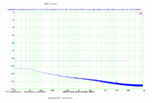
I agree that the measurement with input shorted is telling not much for MM preamps. I measure the noise with input shorted and also with input connected to the real cartridge. Above 2 or 3kHz we may see a contribution of the 47k loading resistor. I would also appreciate if JA used log frequency scale. Lin scale masks eventual poor supply line induced noise rejection.
Gain of the measured preamp is 40dB/1kHz.
Attachments

I will go for 4Just place a 3 transistor discrete buffer on the output of the op-amp inside the feedback loop.
I don't understand the john's problem. Or you need low noise at low levels, and you can set the resistances value low, or you need output buffer, and you don't care about the resistance's noise and/or you can add a buffer as in this schematic.
Attachments
Last edited:
Senses of the trasfo coils.Hello Ed, it's not like you to goof....as far as i can see those two schematics are identical ????.
SY,
Figure 19 is impedance vs frequency a different measurement. You will never see -200 dB (re 1 V) ripple ever in a real circuit. It just ain't possible.
Max,
They are different, it is a where's Waldo difference! But very important. (Hint, there is a reason why a center tapped transformer is not used.)
BTY Thank You for being willing to venture out into the the dungeon of DIY Audio.
That's a hoot and a half!John you're in the wrong business. The add copy here is particularly interesting.
The Bluetooth Hybrid Vacuum Tube Amplifier - Hammacher Schlemmer
SY,
Figure 19 is impedance vs frequency a different measurement. You will never see -200 dB (re 1 V) ripple ever in a real circuit. It just ain't possible.
Max,
They are different, it is a where's Waldo difference! But very important. (Hint, there is a reason why a center tapped transformer is not used.)
BTY Thank You for being willing to venture out into the the dungeon of DIY Audio.
Since the plus supply is connected to the wrong pin, neither will work. 😀
Not our fault if you, sadist Ic manufacturers, decided to place the + and - input pins in the most uncomfortable schematic place.Since the plus supply is connected to the wrong pin, neither will work. 😀
SY,
Figure 19 is impedance vs frequency a different measurement.
Yes, that's how one gets ESL. Have you lost the context so fast?
You will never see -200 dB (re 1 V) ripple ever in a real circuit.
Yes, lost in the noise left over from the Big Bang. But I wasn't the one claiming that this 3k/6k/whatever-new-one-you-come-up-with is significant, that was your claim. I just showed, using your logic but with uncooked books, that it's not even vaguely significant.
Ed, thank you for your welcome, and yes I am very well aware that this meeting ground can be a snake pit of sorts 😱, haha bring it on I say lol.
Thanks Christophe, yes I am the eeediot for not noting Ed's secondary winding polarity differentiating, doh !!!.
This subtle change well causes a 'subjective' difference that I have well noted in the past by experiments involving physically splitting the transformer CT common connection and using dual bridge rectifiers and swapping back and forth individual secondary polarities....ok the individual supply refresh rate is doubled of course, but swapping winding polarities makes a further difference, as should be expected.
My apologies to you Ed for not seeing what should be obvious 😉
Dan.
Friends turning up with JD in hand and posting don't always mix...all friendly though 😉
Last edited:
What? Brian Cheney passed away? Where have I been?Another photo. RIP both of these guys.
Since the plus supply is connected to the wrong pin, neither will work. 😀
Scott,
You made me look! It is 1/2 of a dual opamp!
Would you care to elaborate about how PSSR is measured for data sheet use? I.E. one side at a time etc.
One of the basic things that we all need to remember is that there are almost always different path to follow to the same end. While John may prefer to use discrete components and others may wish to use opa's that does not make one method correct and the other inferior. John came from the time when the change from fire bottles to solid state were in themselves just as large a fight for the hearts and minds of EE's as today's choices of discrete or IC topology. This will go on for a long time to come.
I think of my first cellular phone, an old Nokia and how small that was compared to a land line phone. It did one thing, it made phone calls. As time has passed more and more functions have been added, now you can surf the net or even do some analysis with your Iphone and some freely downloaded app. Me I am still waiting for my Dick Tracy watch that does it all on my wrist with a holographic display. But back to that basic phone, the premise was that they would keep getting smaller and look where we are today. People are asking for larger and larger screens while I am saying what do I want to carry that large device for? Different things for different people, but when I only want to make a phone call is there a real difference in the quality of the call, not that I can hear. So we can all I see agree that one method will never satisfy everyone, that is what makes all this so interesting.
I think of my first cellular phone, an old Nokia and how small that was compared to a land line phone. It did one thing, it made phone calls. As time has passed more and more functions have been added, now you can surf the net or even do some analysis with your Iphone and some freely downloaded app. Me I am still waiting for my Dick Tracy watch that does it all on my wrist with a holographic display. But back to that basic phone, the premise was that they would keep getting smaller and look where we are today. People are asking for larger and larger screens while I am saying what do I want to carry that large device for? Different things for different people, but when I only want to make a phone call is there a real difference in the quality of the call, not that I can hear. So we can all I see agree that one method will never satisfy everyone, that is what makes all this so interesting.
- Status
- Not open for further replies.
- Home
- Member Areas
- The Lounge
- John Curl's Blowtorch preamplifier part II