Scott, I agree, talk to yourselves. I don't care. However, I am not in a position to talk about Ayre's EquiLock, AND if you had any sense of history, you would find that the CTC design is a stripped down version of Charles Hansen's early preamp, WITHOUT current mirrors.
John, why don't we just talk about circuits and getting a job done. i could care less about enlessly crediting so and so with this or that connection of transistors.
Everyone, I like to attribute where the design comes from, because often people just take, what was initially developed by individuals, most of whom I know, in the past, and they deserve credit for it.
For example, Bob Cordell's design topology is derived essentially from Dick Burwin's work in the 1960's for Analog Devices.
I think that Dick Burwin deserves some credit for his early effort. Just my opinion, perhaps, but then I will take credit for what I have developed on my own, over the decades, because I think that I deserve it. It was new and fresh, when I first tackled the problem. Just because 'everybody' uses it today, doesn't make me forget how difficult it was to convince anyone in the late 1960's to use it, since it seemed so 'over the top' at the time.
I agree, and am reconsidering ignore lists. Start a thread and talk about real circuit issues. You won't get all the free hits that JC generates, but I'm sure the net value will increase.
I agree and I think you should give it a try. It could be a very interesting thread; maybe not as many postings as in the BT thread but I’m sure a lot of people will read it.
Who knows maybe some people that don’t post in the BT thread will post in the new thread as well. And if the moderators could let the discussion go on without splitting it up and placing different parts in the Solid State, Analog Line level and Analog Source forums it would make it a lot better.
Place the new thread in the Solid State forum that’s where it belongs.
Cheers
stinius
John, why don't we just talk about circuits and getting a job done. i could care less about enlessly crediting so and so with this or that connection of transistors.
Yes, I can't see why people MUST post here for their circuit discussions, then complain because it is the same as it ever was. If you guys have circuits to discuss, why not do it in a thread that doesn't have such baggage.
It seems that people want to show off in front of the "crowd" not really discuss circuits. Then complain bitterly that people posting aren't to their liking ..
This thread clearly is about more (or less actually) than circuit design. In a circuit design thread, it would be off topic to discuss other than circuit design and posts that were off that topic would be deleted..
Mark
Last edited:
One factor that continues to haunt me is WHY we don't use coupling caps at inputs and outputs, if possible.
Of course, decades ago, caps were everywhere, including between stages.
Why don't we use them, anymore?
Well, let me give you a quick history of the use of caps in audio equipment over the last 70 years or more.
First, the coupling caps, between stages, were made with a wax paper material and they were called paper caps. They had a lot of DA, but were fairly linear.
Marantz was one of the first companies to use Mylar caps in their preamps. They even kept it a secret. Mylar was better than paper, for hi fi, but still not perfect.
When solid state came in, even Mylar failed to be large enough in capacity to do the job properly, so we went to Tantalum, aluminum, or sometimes we even used high value ceramic caps. In those days, the '60's, tantalum did a pretty good job, so long as we stuck to SINGLE power supplies, so that we put a bias on the caps.
By 1970, we started using plus and minus supplies, because of the influence of IC op amps that started to be used in a lot of equipment. Then the Tantalum caps generated high distortion at bass frequencies. The high value (.1-2uF) ceramic caps were really, really bad, and had all kinds of distortion, but many audio engineers still used them, because they were non-polar, small, and kind of pretty.
It took a lot of published measurements to remove most of these cap problems, and many people are still stubborn about it today. However, we thought that polycarbonate caps were pretty darn good, and we used them. Toward the end of the '70's even polycarbonate was suspect (we could hear it) and we tried to remove the coupling caps completely. We were in luck that affordable jfet input op amps became available and affordable, by this time, so we went to servos, to keep the offset low.
Later, Walt Jung, Scott Wurcer, and I started looking into dielectric absorption in caps. This was a completely separate mechanism (for all practical purposes) from the non-linear distortion measured primarily in Tantalum and ceramic caps in the '70's. It, in fact, could sound kind of nice, except it was a departure from ideal sound reproduction. Some people still use it today, to make interesting sounding equipment, mostly musical instrument amplifiers and preamps.
By the middle 1980's we knew a lot more than the textbooks gave us about caps, but some people, including Doug Self, refused to believe it at all. He has changed his opinion today, to some degree, I am pretty sure, and he and other people have taken our earlier work and run with it in recent years, sometimes improving on it, sometimes confusing many people, depending. And so it goes.
Last edited:

There is no 'perfect' capacitor. It is best to avoid them, in audio coupling, if you can.
They always have a series of trade-offs. Some have virtually perfect dielectrics, with virtually no DA, but they they might be more subject to vibration than some other caps with slightly higher DA, but are smaller in size.
They always have a series of trade-offs. Some have virtually perfect dielectrics, with virtually no DA, but they they might be more subject to vibration than some other caps with slightly higher DA, but are smaller in size.
Everyone, I like to attribute where the design comes from, because often people just take, what was initially developed by individuals, most of whom I know, in the past, and they deserve credit for it.
For example, Bob Cordell's design topology is derived essentially from Dick Burwin's work in the 1960's for Analog Devices.
I think that Dick Burwin deserves some credit for his early effort. Just my opinion, perhaps, but then I will take credit for what I have developed on my own, over the decades, because I think that I deserve it. It was new and fresh, when I first tackled the problem. Just because 'everybody' uses it today, doesn't make me forget how difficult it was to convince anyone in the late 1960's to use it, since it seemed so 'over the top' at the time.
Hi John,
Are you referring to my MOSFET EC amplifier design?
I'm curious, can you share with us the Burwin design or reference you speak of?
As you know, mine is at Cordell Audio: Home Page.
BTW, I assume you are not referring to the MOSFET output stage (they didn't have power MOSFETs back then), or the EC, which was put forth first by Hawksford, to whom I have always given credit for the basic idea.
Thanks,
Bob
Yes, just go to Walt Jung's website, and look at op amp history.
John,
Just what I expected of you. No back-up for your reckless statements. Why don't you post specifically what you assert is the same? You never want to be corned. You won't even be specific about the circuit part you are referring to. If you remember it, it is easy to say in 25 words or less.
You made the assertion, you back it up. And if you can't, or won't, don't whine about it when somebody accuses you of making up stories that may be less than truthful.
My you-know-what meter remains pegged.
Bob
What is wrong with you, must I spoon feed you to find the schematic on Walt's website? Look at it. It is your basic topology, that you, and many others have used over the decades, including Marantz, with the #'s 14 and 15 power amps, where I found this topology first used.
What is wrong with you, must I spoon feed you to find the schematic on Walt's website? Look at it. It is your basic topology, that you, and many others have used over the decades, including Marantz, with the #'s 14 and 15 power amps, where I found this topology first used.
John I don't know what you are refering to. Dick's early stuff was totally ordinary discrete op-amp circuits. Two stage, dominant pole, etc. He used FET inputs, not profound in retrospect considering Philbrick used tubes in 1952.
Please Scott, not you too! Look at his 1966 topology for a hybrid op amp. It is essentially a first diff, second diff, mirror turn-around, and output. 100V/us too! Let's give him a little credit.
If you want to see something closer to what Bob uses, in terms of fets, look at the op amp design of the Levinson JC-2 phono stage. I have jfets on the input and output.
Even closer, the Spectral op amp schematic.
If you want to see something closer to what Bob uses, in terms of fets, look at the op amp design of the Levinson JC-2 phono stage. I have jfets on the input and output.
Even closer, the Spectral op amp schematic.
Last edited:
What is wrong with you, must I spoon feed you to find the schematic on Walt's website? Look at it. It is your basic topology, that you, and many others have used over the decades, including Marantz, with the #'s 14 and 15 power amps, where I found this topology first used.
John,
There is nothing wrong with me. The problem is you. You cast dispersions on other people's work (mainly those who disagree with you) and then do not have the courtesy to be specific about your criticisms and back up what you say. This happens all too frequently with you, and I and others frankly get tired of it.
Its on you to explain what you say, and it is not spoon feeding for you to do that. I should not have to spend hours wading through Walt's very good web site only to discover that what you are saying is based on an unsupported extrapolation on your part.
As Scott pointed out, there is nothing particularly new or novel about using a differential pair VAS with a current mirror on the other side. I never said there was. In fact, I never made a claim that my input IPS-VAS was novel. However, I am also unaware of a prior implementation that has all of its features. In particular, show me where Dick Burwen loaded his IPS with a differential current source load with common mode rejection of current.
BTW, I'm sure you also get a bit wrangled when other people assert that you were preceded by Bogiorno in coming up with the complementary differential input stage.
Bob
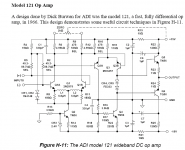
This one is closer to what I was thinking. So OK Dick deserves some credit for working in the early days. Some of it did not translate to IC's well (like the input L's). This circuit has the basic elements, diff in, current mirror loaded, cascoded darlington VAS, dominant pole compensation. I'm not sure this is Dick's but it's from the same time(?). The part ID's are suspicious so I'm not sure.
Attachments
- Status
- Not open for further replies.
- Home
- Member Areas
- The Lounge
- John Curl's Blowtorch preamplifier part II