Hmmm... yes, lets call it a draw or merely a flesh wound. This audio stuff is almost as bad as that pesky Higgs boson.
I agree it can get pretty strange at times and emails and forums are limited in what can be conveyed...
with my great respect to you - Thx for the feedback to my two cents worth -- RNM
I did more times test very similar as in setup posted here,with real music source (CD, HD music),and with realistic values for coupling cap for line stages (e.g. 100uF and load 1k), but dif amp. with gain=1, and output from this dif amp added in correct proportion (via "distortion" switch in path..)to the same music signal and fed to input of "control amplifier" with loudspeaker conected. Try to identify in blind test if "distortion" switch is on or off..🙄
Do not overestimate our (yours)ears. "Audibility" of many effects in this test dissapear..
Do not overestimate our (yours)ears. "Audibility" of many effects in this test dissapear..
Last edited:
Try to identify in blind test if "distortion" switch is on or off..🙄
Do not overestimate our (yours)ears. "Audibility" of many effects in this test dissapear..
Yes BV. Scott made the same comment early on here:
The key is to assess the audible importance of the errors, that is where we have some disagreement
I guess there is an issue usually overlooked when thinking about lowest limits of detectable distortion.
While listening, the critical bands of our listening mechanism can play many tricks with minute levels of generated high harmonics. If they happen to fall within the same critical band with music content, the ear detect them and perceive something is wrong.
This is a dynamic effect and can not be easily - if at all- simulated for measurement purposes.
George
there could be a lesson from perceptual lossy compression codecs at 320k - where the latest codecs are "transparent" - even to the developers who train on the artifacts - for virtually all "music"
they only use ~ 7 bits per critical band to encode levels - ~ 1% frequency content relative accuracy seems to get us a long, long way in audio perception - as long as we can log range
better film, NP0/C0G dielectrics DA errors only give milli or micro dB frequency response differences in most audio continuous filter/coupling applications vs the 0.1 dB = 100 milli dB jnd threshold
Last edited:
I agree it can get pretty strange at times and emails and forums are limited in what can be conveyed...
with my great respect to you - Thx for the feedback to my two cents worth -- RNM
Mutual respects of course, this online interaction has its limitations.
there could be a lesson from perceptual lossy compression codecs at 320k - where the latest codecs are "transparent" - even to the developers who train on the artifacts - for virtually all "music"
they only use ~ 7 bits per critical band to encode levels - ~ 1% frequency content relative accuracy seems to get us a long, long way in audio perception - as long as we can log range
better film, NP0/C0G dielectrics DA errors only give milli or micro dB frequency response differences in most audio continuous filter/coupling applications vs the 0.1 dB = 100 milli dB jnd threshold
We have come a long way, indeed, from the days when Bart Locanthi auditioned some of the early codecs and pointed out things that, once noticed, were clearly audible to all. Allegedly the developers had already used a large panel of listeners who had reported nothing, and were content to leave the designs unchanged despite Locanthi's observations.
I listen happily (albeit with appropriately low expectations) to music in more-or-less real-time over the internet, with a medium-speed DSL connection, on Stickam on the "Hank and Jim Radio Network", although the bigger draw is mostly chatting with friends there. Talk about a means that has come a long way! I recall an AES demo many years ago where the presenter, at the end of a talk, had some real-time internet audio playing. It sounded beyond dreadful, distortions of such variegated forms as to require whole new vocabularies. The presented said "Well, it's only 8 bits". As was then my custom late of a Sportsmen's Lodge evening, I somewhat aggressively pointed out that 8 bit uncompressed dithered audio could sound very good indeed by comparison to the demo. However, being hypercritical in those days of "a bear riding a bicycle" was churlish --- it was amazing that it worked at all.
Brad
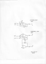
> (opposing diodes???)
Opposing capacitor DA buster:
What is this circuit supposed to do ?
This audio stuff is almost as bad as that pesky Higgs boson.
Similarly, as my use of terms is broad:
- particles which have no mass should not be called particles.
Last edited:
Audio amplifier output stage with voltage gain.What is this circuit supposed to do ?
Since the voltages accross the caps oppose,
but then the signal is combined, the capacitor
distortions cancel.
Last edited:
I first started to talk about using coupling caps between stages and in the feedback loop, in order to show an alternative approach by using servos. I have not gotten very far.
Back in the days when we thought that coupling caps were an important problem, about 1980, due to the articles by Dick Marsh and Walt Jung, along with my earlier measurements of nonlinear distortion in Tantalum and Ceramic caps. Serious audio designers had to figure out what to do? Do we use bigger and better coupling caps, or do we direct couple? And IF we direct couple, can we get away with it, without all kinds of trouble keeping the DC offsets in check, over time and temperature?
First, let me set the low limit of the value of capacitance at 1uf. This is for a number of reasons, but with bipolar inputs, you are just asking for it, if you use a smaller value. Of course, tubes and jfets COULD allow for a somewhat lower value, but then the price would increase just using these parts, so let's stick to 1uf.
What is available, today, or back 30 years ago, that might fill the bill?
Well, if you are Sony, then you might select a large value ceramic. It would be smallish, non-polar, rugged, and compatible with large scale assembly.
Some high end people might want to use a film cap, instead. Back in 1970's, I thought that 1uf Mylar coupling caps, since they did measure well, with a sine wave measurement. Darn, if somebody didn't 'hear' them and got me to remove them from one of my Xover designs. Well, what next?
Polystyrene gets really big, Teflon too, AND EXPENSIVE. Polypropylene isn't bad, it measures well, and has no obvious problems. Still, it is fairly large, and not dirt cheap, that is, if you want one from an established manufacturer. Now what is the alternative? You could use an aluminum electrolytic cap, of course you can go up much higher in capacitance, for a given case size. However, this could well be the fundamental limit on your design's lifetime. We certainly find that with test equipment. Over time, we find that aluminum electrolytic caps are often the first thing to go, even if used correctly and from a reputable manufacturer. Also, it might be noted that not just ONE capacitor is used, often you have in-out, feedback and interstage coupling caps. They kind of add up. That is why we thought that servos were a useful way to minimize the coupling cap problem, substituting an IC op amp (single or dual) and adding a couple of resistors and a 1uf Mylar cap was a useful alternative. (more later)
.... (more later)
I am all ears !🙂
As an aside, is there a better name for "servos" ? I always thought this name doesn't describe very well the purpose of the circuit.
I would call them "DC cancellation circuits" or maybe "DC negative feed-back loops" or just "DC loops".
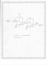
Here is another servo example, one that I prefer, today.
Hi John,
Thanks for the schematics.
Why two IC's when one would do (connected to the (+) input)?
That would require an input coupling cap, which sorta defeats the whole purpose of the servo.
That would require an input coupling cap, which sorta defeats the whole purpose of the servo.
Sy, how can you have a coupling cap in what is a DC amplifier? The first stage of JC's servo is an inverting low pass filter and you can do the same non-inverting, so I guess Joshua is right and save one opamp. But it might be good to maintain the second opamp as a buffer though, because stuff will be coming from the other end (feedback loop).
vac
Last edited:
That would require an input coupling cap, which sorta defeats the whole purpose of the servo.
Thanks.
Sy, how can you have a coupling cap in what is a DC amplifier? The first stage of JC's servo is an inverting low pass filter and you can do the same non-inverting, so I guess Joshua is right and save one opamp. But it might be good to maintain the second opamp as a buffer though, because stuff will be coming from the other end (feedback loop).
vac
It's after midnight here and I'm too tired to follow AC vs. DC gain right now. One IC (without a series input cap.) may work and it may not.
- Status
- Not open for further replies.
- Home
- Member Areas
- The Lounge
- John Curl's Blowtorch preamplifier part II