the "partial mutual inductance" approach can model proximity, skin effects
FastHenry extraction program can be ran at multiple frequencies, and a Spice compatable higher order model that fits the multiple frequency points can be auto gnenerated by the SW
the limtation of is that no radiation or displacement current terms are used, can't model multiple propagation modes, any "wave" behavior
the FastHenry modeling should still be informative for GHz op amps where the circuit dimensions are easily < 1/10 wave
Last edited:
Maybe he could start a new business, and supply quality demos. It would be a service to the audiophile community, but he has to do more than one or two customers to make a difference.
SY,SE and Scott, are too “stiff” for this new S&M
The Art-Deco on the TASCAM and on the reels says it all.
After a while, the original 2nd WW tape recorders will show up as the ultimate stuff to have, but some here will argue that there are no original (pure iron oxide) tapes around.
Bcarso
Thank you for the link.
Jneutron has mentioned silicon substrate is a big problem on the IC speed (I can’t find his post)
the "partial mutual inductance" approach can model proximity, skin effects
FastHenry extraction program can be ran at multiple frequencies, and a Spice compatable higher order model that fits the multiple frequency points can be auto gnenerated by the SW
the limtation of is that no radiation or displacement current terms are used, can't model multiple propagation modes, any "wave" behavior
May be Scott has something to say on this ( I wish)
George
1/3 centyry??
would that be 33 1/3 years perhaps???😉😉
Actually, we can do better, especially at both low and at extended frequencies above 20KHz (for superior transient response). I hope to show interested people, how. We did this about 1/3 century ago.
would that be 33 1/3 years perhaps???😉😉
The Art-Deco on the TASCAM and on the reels says it all.
Ah, that's what it is ?
You've been reading the brochure ?
Sheesh. That close to what mine cost, and I did all the labor,radiant heat, cabs, appliances, porclean tile. Much higher if you pay someone..Most kitchen remodels cost more than high end audio systems, with the average reputed to be $45K and premium ones costing much more.
Yah, it slows the prop velocity for stripline traces on the surface. Copper has sped it up a bit though.Jneutron has mentioned silicon substrate is a big problem on the IC speed (I can’t find his post)
jn
Sigh..it was only a matter of time until they started stacking the dice.😉
After all, most of the silicon is inert anyway. Chips I worked with were 13 mils to 25 mils thick, and the bulk of the device is on the surface.
I wonder how they make the vias?.
jn
Ah, but the loss of natural tape compression; Many have expressed this as a regrettable thing that given the choice they would rewind😀It's not. Use good mikes, a decent ADC, and make use of the wide dynamic range to prevent ever hitting the red line. Like I've said, I spent years using some pretty good analog tape equipment, and I'd never go back.
and I did all the labor,radiant heat, cabs, appliances, porclean tile.
Mr John,
can i interest you in a membership of the butch nerd club ?
(friday is bare-knuckle night, followed by a nice game of chess)
Mr John,
can i interest you in a membership of the butch nerd club ?
(friday is bare-knuckle night, followed by a nice game of chess)
Too late..already a lifetime member...😉
Getting ready to gut a bathroom in a few weeks...the only thing I hate but do...spackle..man, am I challenged there..

Wallpaper, I will NOT do. Crown moulding for the kitchen cabinets used to be bad...until I figured out a double cut was needed. One close to size to allow wood relaxation, then a final shave to size..
jn
I ran into my friends Paul and Claire at another's birthday party Sunday. A very busy couple with active careers, although Paul retired from his high-powered academic job at UCLA (composer/professor) a few years ago.Too late..already a lifetime member...😉
Getting ready to gut a bathroom in a few weeks...the only thing I hate but do...spackle..man, am I challenged there..
Wallpaper, I will NOT do. Crown moulding for the kitchen cabinets used to be bad...until I figured out a double cut was needed. One close to size to allow wood relaxation, then a final shave to size..
jn
Paul builds about everything in what has become according to another friend their "compound". He's always delighted to get inspections as virtually everything is well beyond code requirements. This penchant for construction and/or modification extends to Hi-Fi equipment.
May be Scott has something to say on this ( I wish)
George
We have these capabilities but usually you need an expert driver for the tools. Garbage in garbage out. Our modeling folks are now supporting us at up to 50G with some amazing fits to the data. I think they rented a 90G network analyser at the time to verify, I think there are 1050G ones now.
They is a lot to be said for tape compression. We used to record very hot, or "pack it on". Kept everything up out of the noise and most tape formulations in the 80s-90s could take it. Some compression does sound good, tape especially.Ah, but the loss of natural tape compression;
Well, to continue. I found an approach that is somewhat unusual to 'fix' the 30 ips low frequency head bump problem.
But first, I would like to comment a little on where the 'head bumps' come from, AND the added low frequency roll-off below the head bump peak.
The low frequency response limit of a magnetic head is the WIDTH of the reproduce head, itself. Therefore at 30 ips, a VERY WIDE head keeps the low frequency response from following off. The CONTOUR of the head and how it fits the tape passing by it, is what makes the EXTRA ripples in the low frequency response. Many years ago, Bogen (Germany) and others adapted a contour that had a SINGLE bump, and this was easier to make flat.
The Supermaster (1979) used an AMPEX type head, and had a more complicated head bump structure, so it took MORE to equalize it, but the Ultramaster (1983) that Dave Wilson still owns, uses STUDER heads, and they are the 'single bump' contour, so easier to make a very flat frequency response. Of course, below 15 ips, this head bump business, becomes almost unnecessary to worry about. It only becomes important at high speeds.
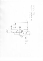
Now to describe the 'fix':
Looking at the head bump graphically, I noticed that it looked essentially like a 2 dB (or so) peak, 2 pole Chebyshev hi pass filter. I wondered how I could make its 'complement' in a straightforward way. Of course, gross EQ would sort of work, but would that really give the 'transient response' and the 'best fit' for the problem.
I realized that if I could 'emulate' the head bump with a Chebyshev filter, AND put it in the feedback loop, somehow, I could better flatten out the low frequency characteristic.
So, I tried a number of computer solutions, until I got it pretty close.
This was so much better than the Ampex or the Studer solution to the problem, that it was probably patentable at the time, but that was a long time ago.
Next, I will show a partial solution to the problem.
But first, I would like to comment a little on where the 'head bumps' come from, AND the added low frequency roll-off below the head bump peak.
The low frequency response limit of a magnetic head is the WIDTH of the reproduce head, itself. Therefore at 30 ips, a VERY WIDE head keeps the low frequency response from following off. The CONTOUR of the head and how it fits the tape passing by it, is what makes the EXTRA ripples in the low frequency response. Many years ago, Bogen (Germany) and others adapted a contour that had a SINGLE bump, and this was easier to make flat.
The Supermaster (1979) used an AMPEX type head, and had a more complicated head bump structure, so it took MORE to equalize it, but the Ultramaster (1983) that Dave Wilson still owns, uses STUDER heads, and they are the 'single bump' contour, so easier to make a very flat frequency response. Of course, below 15 ips, this head bump business, becomes almost unnecessary to worry about. It only becomes important at high speeds.
Now to describe the 'fix':
Looking at the head bump graphically, I noticed that it looked essentially like a 2 dB (or so) peak, 2 pole Chebyshev hi pass filter. I wondered how I could make its 'complement' in a straightforward way. Of course, gross EQ would sort of work, but would that really give the 'transient response' and the 'best fit' for the problem.
I realized that if I could 'emulate' the head bump with a Chebyshev filter, AND put it in the feedback loop, somehow, I could better flatten out the low frequency characteristic.
So, I tried a number of computer solutions, until I got it pretty close.
This was so much better than the Ampex or the Studer solution to the problem, that it was probably patentable at the time, but that was a long time ago.
Next, I will show a partial solution to the problem.
Sigh..it was only a matter of time until they started stacking the dice.😉
After all, most of the silicon is inert anyway. Chips I worked with were 13 mils to 25 mils thick, and the bulk of the device is on the surface.
I wonder how they make the vias?.
jn
Through wafer vias, backside holes, laser drilled alignment holes (connectors directly to the silicon) all available at a price. We don't do it but I even saw someone backgrinding 12" wafers to 10 microns.
BTW have you seen the project to stack a mole of silicon atoms into a perfect cube as a new mass standard?
Through wafer vias, backside holes, laser drilled alignment holes (connectors directly to the silicon) all available at a price. We don't do it but I even saw someone backgrinding 12" wafers to 10 microns.
Sheesh. I'm still trying to figure out how they get the toothpaste in the tube.. perhaps it should be on "How it's made".
BTW have you seen the project to stack a mole of silicon atoms into a perfect cube as a new mass standard?
I was offered a key position in that project, but I regretfully turned it down. Yes, somebody does have to count to make sure they have exactly 1 mole, but since it involved a number higher than ten, it would have required my removing my shoes.
Scientists think of the weirdest things...I thought I was bad.
jn
Sheesh. I'm still trying to figure out how they get the toothpaste in the tube.. perhaps it should be on "How it's made".
I was offered a key position in that project, but I regretfully turned it down. Yes, somebody does have to count to make sure they have exactly 1 mole, but since it involved a number higher than ten, it would have required my removing my shoes.
Scientists think of the weirdest things...I thought I was bad.
jn
This reminds me of a Trader Joe's brand of guacamole, Avocado's Number. For me the best part of the packaging was a portrait of Avogadro, captioned with his invitation to party.
John, that is BRILLIANT !I realized that if I could 'emulate' the head bump with a Chebyshev filter, AND put it in the feedback loop, somehow, I could better flatten out the low frequency characteristic.
I've failed to se a HP filter with Chebyshev characteristic there when I looked at your graphs, I have to admit. Now it's obvious.
Attachments

- Status
- Not open for further replies.
- Home
- Member Areas
- The Lounge
- John Curl's Blowtorch preamplifier part II