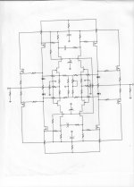

OK, first question, what sets the (approximate) current limit of each jfet on the CORE schematic?
Well, to me the main difference is inclusion of multiple feedback loops in the later design, although it's difficult to analyze it exactly without knowing the ratios of all resistors that are connected to all four Fet sources.
Best,
Best,
Last edited:
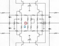
But isn't the ground (0V) in the middle implied ?
But yet if hardwired turns the whole thing class B
But yet if hardwired turns the whole thing class B
the resistor in the middle ?
Yea ....... Center tap it to ground (0V)
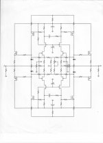
If you split the resistor in the middle in halfIt does NOT need a ground reference, except at the inputs.
and put a test probe in the middle .........
What should you see ?
the middle resistor sets the operating current of the four JFETs
one of feedback resistors will reference the JFETs to ground
.
one of feedback resistors will reference the JFETs to ground
.
Last edited:
If you split the resistor in the middle in half
and put a test probe in the middle .........
What should you see ?
Distortions of input ignal.
More questions? 😉
“I wake up and I see the face of the devil and I ask him, 'What time is it?' And he says, How much time do you want?”
"Never speak with strangers."
Mikhail Bulgakov
.
Last edited:
Hi JC,
What is it?
Erno Borbely's articles in Audio Amateur in the 70-ies. Only he managed to do it with all FETs. ;-)
jan
Last edited:
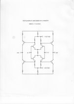
Parasound JC-2 simpified
The link should bring you to post #1515
Add the output buffer's (LED's, resistors (trimpot's) and MOSFET's shown in previous post by John) and feedback resistors.
Two of the components are wrong in the schematic I posted.
Cheers
Stein
http://www.diyaudio.com/forums/analog-line-level/146693-john-curls-blowtorch-preamplifier-part-ii-152.html#post1931584
Last edited:
Hi,
For you, probably. For me it is "kleingeld" (small money).
Ciao T
So, small change is "gelding"? Sorry, couldn't resist....
For you, probably. For me it is "kleingeld" (small money).
Ciao T
Hi Johnless tilted
What's the connection in the center of the diagram for? (aside from "NOT GROUND, DAMMIT!" 😀)
Is it just a test point?
p.s. Looking at it again, it seems that common mode voltage at the input will be transferred to the output, albeit not amplified. Is that not a concern? IIRC, one of Nelson's topologies does the same thing.
Attachments
Last edited:
- Status
- Not open for further replies.
- Home
- Member Areas
- The Lounge
- John Curl's Blowtorch preamplifier part II