How wonderful! Do we know the dramatis personae?
Johnny Wayne, Frank Schuster and Sylvia Lennick
50 years since she said, 'Julie, don't go!' - thestar.com
Wayne and Shuster - Wikipedia, the free encyclopedia
Johnny Wayne, Frank Schuster and Sylvia Lennick
50 years since she said, 'Julie, don't go!' - thestar.com
Wayne and Shuster - Wikipedia, the free encyclopedia
Excellent! Thank you. I must have seen that the first time it was on network TV. A long time ago, indeed.
Clearly, it made an inedible impression on my young mind.
Everyone, could we go back to audio design? I realize that some don't think it very useful or important, but it is the reason for the length and attendance on this thread.
In my world, today, I have several assignments:
One is to replace 2SK389's with 2SK170's or LSK 170's. This requires some sort of matching scheme to get good offsets, that is a 'piece of cake'.
The next is to troubleshoot a serious phono stage design with about 50 jfets per channel, sorry I can't get into detail about that.
Third, is to design an op amp containing headphone amp of high quality. We can talk about that, and WHY I did it the way I did.
Any questions?
Actually Ramona caused a bit of a stir when it was first tested. It seems the transmitter bounced off the Ionosphere and was picked up on all sorts of gear in the U.S. leading folks to wonder if it was some sort of deliberate jamming or electronic warfare!
It was completely passive system, with no transmitter. There is some description in
http://www.raf.mod.uk/rafcms/mediafiles/49889B7E_1143_EC82_2E34B486AD92DC17.pdf
article "Silent Trackers: The Spectre of Passive Surveillance in the Information Age"
"Third, is to design an op amp containing headphone amp of high quality. We can talk about that, and WHY I did it the way I did"
I'd just come clean and say if you are after top quality its really a no brainer.
I'd just come clean and say if you are after top quality its really a no brainer.
I remember the surprise when the Serbs shot down a US stealth bomber. At the time it was said that they were using passive radar based on broadcast transmitters. A stealth bomber may be 'invisible', but it is still opaque.
Underestimating your enemy seems to be a standard military tactic. Are people taught to think in straight lines at staff college, or is it that the armed forces only recruit unimaginative people?
Underestimating your enemy seems to be a standard military tactic. Are people taught to think in straight lines at staff college, or is it that the armed forces only recruit unimaginative people?
Underestimating your enemy seems to be a standard military tactic.
Not only military tactic - this thread is a real proof. I would not speak about 'enemy' in this thread, but actually underestimating of potential competition or of different design approach is a standard tactic here, rather than open unprejudiced discussion. And for this reason it lost any attractiveness regarding audio design.
The next is to troubleshoot a serious phono stage design with about 50 jfets per channel, sorry I can't get into detail about that.
Third, is to design an op amp containing headphone amp of high quality. We can talk about that, and WHY I did it the way I did.
Any questions?
Do you plan to make phono stage integrated with high quality headamp?
That would be new, a system including no digits, only vinyl and high-quality low-wattage analog schematics.
I have been making phono preamps for the last few years. However, I can only talk in general about the designs, because they are not even released yet.
I feel a little differently about the headphone design, because it is a Honda and not a Porsche.
I feel a little differently about the headphone design, because it is a Honda and not a Porsche.
It was completely passive system, with no transmitter. There is some description in
http://www.raf.mod.uk/rafcms/mediafiles/49889B7E_1143_EC82_2E34B486AD92DC17.pdf
article "Silent Trackers: The Spectre of Passive Surveillance in the Information Age"
Apparently either during development they used a simulation of US AWACS or there was some other source. At the time it was called in the U.S. "Mocking Bird" and thought to Soviet over the horizon radar.
I will give a brief description of the headphone amp that I just developed. It is not the finest possible headphone amp that I can conceive of, but it is buildable, cost effective, and does not require many components. Done right, it should satisfy more than 95% of all needs in this area. Still, it is NOT a Blowtorch, or designed to be as good as one.
First, the requirement of what must be done by the headphone amp (HPA), what its output should be and the loads that it might be put on it.
Second, it must be realized that ANY higher order distortion through especially good headphones might well and easily be a distraction and even give headaches, etc.
Third, the part count in this design should be minimized to save space and cost, it will become expensive enough with the case added, etc.
It is important to not go too cheap and simple. For example, a SINGLE or a dual IC might do the whole job in a mid-fi design. That just won't do. The 'starved' nature of the op amp outputs will surely not be happy with 30 ohm, for example, loads, and will sound lousy over time. (just my opinion) More later.
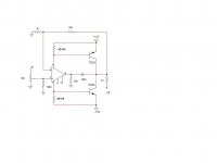
The approach that I selected is a little unconventional. I did not invent this topology, I got it from an IC manufacturer's app. note published around 1970, when I made my first version.
This design uses an IC as the main amplifier component, but augments it with two complementary output devices DRIVEN FROM THE POWER SUPPLY CONNECTIONS of the op amp, in most cases, pins 4 and 7. Done right, and running Class A, this little circuit can drive K-horns or used in even automotive applications as a small amp.
As the output devices are essentially connected to the power supply rail(s), this sort of output is extremely efficient in utilizing what power supply you have available.
I have used this sort of design for decades, off and on, for driving K-horns, JBL's on the road, making an NAB reference amplifier submission,(to replace the All American 5 tube radio) and more. It is one of those design approaches that appears to do better than you would expect it to. Why, I do not really know. (more later)
Last edited:
Yes that is an interesting topology, very efficient indeed.
I hope you're giving us some more details!
jan
I hope you're giving us some more details!
jan
That configuration is appealing IF one is confident of the distribution of opamp quiescent current. Once again, for manufacturing, one is at the mercy of a process capability. One can observe and test until the cows come home and, unless the part is specifically guaranteed to have a sufficiently tight distribution, you may ship 10k units and find that the next 10k run barely works.
besides possible idle current variations,
with easy runaway, that circuit has the
propensity to be squirrelly as H*ll
compensation wise ........
with easy runaway, that circuit has the
propensity to be squirrelly as H*ll
compensation wise ........
I've both worked with power amps based on this approach, and as well considered its use in designs for many years, and it's from experience, not just inspection, that I render that cautionary note.
I think it's a fine circuit for experimentation and the learning process, and very much in the spirit as I perceive it of diyaudio.com . I would caution against those who, however, on the basis of a prototype or two, go out and decide to make a bunch and sell them (or whatever).
It's minimal parts (pleasing the minimalists, and reducing the odds that parts will be hooked up incorrectly in a breadboard). It swings nicely to the rails, definitely a plus, although the devices could saturate and have storage time effects and hence shoot-through currents for high level high frequency signals. Unlikely to be a problem with real musical signals and headphone listening though. The opamp couples via the cap to drive the output directly for small signals/high frequencies, also a good thing.
I've considered variants where, in place of the resistors labeled "optional" I used a diode-connected small-geometry transistor thermally coupled to the output device adjacent. Less loop gain when the big guys are adequately biased, but lower local distortion. However the big guy self heating will not couple quickly enough to the small ones, nor will there be any accounting for Early effect in the power devices or base-emitter voltage modulation.
Another variant when the quiescent current variation is a concern: an operational transconductance amp in place of the opamp. Its quiescent current can be readily adjusted and is as well well-determined. The problem is the only ones are ancient parts with lateral PNPs in the upper current mirrors, slow dogs indeed, and the absence of emitter degeneration in those Wilson mirrors results in high noise referred to the input. But were it not for these drawbacks, the OTA could allow some temperature compensation of the programming current to partially account for the output device quiescent temp.
Brad
- Status
- Not open for further replies.
- Home
- Member Areas
- The Lounge
- John Curl's Blowtorch preamplifier part II