I built a battery powered amplifier that uses a Sure ME-DV42331 voltmeter display. I burned out 3 of these displays before I finally realized my mistake (I think). The display is inline with the charge circuit. That means both the battery and the charger are feeding into it. The display is meant to check the voltage of the battery and is switched, working outside of amplifier circuit.
The battery is 24V. This means it tops at 29V. Whatever voltage the smart charger is pumping in probably puts me over the 30V max of the Sure display. Oddly, the display works fine all the way through the end of the charge. But the next time I check the amplifier charge after charging, magic smoke--it's happened 3 times like that. So I am assuming the issue is over voltage.
Upon figuring out the issue, I've been disconnecting the display during charging. This is not ideal. Assuming the display is a voltage limit issue, I would like to reconfigure that. However, I have neither the knowledge nor SMD skills to inspire faith. So I am wondering if someone would be interested in doing this for a fee? Option to mod a new display or repair/mod my 3 mistakes. I assume this is just a matter of replacing caps with ones that can handle 48V or something. Thanks
The voltmeter cost $14.00, it's not worth modifying.
Try this Murata DC voltage monitor measures up to 50vdc. Datasheet (pdf)
It's available from Digikey, Mouser, Newark for about $30.00
Try this Murata DC voltage monitor measures up to 50vdc. Datasheet (pdf)
It's available from Digikey, Mouser, Newark for about $30.00
Last edited:
I assume this is just a matter of replacing caps with ones that can handle 48V or something. Thanks
Well if that was the case, you would do it yourself, no?
Jan
Well if that was the case, you would do it yourself, no?
....I have neither the knowledge nor SMD skills to inspire faith.....
Heath Robinson fix.
2 resistor Voltage divider.
Scale to 1/10th and mentally move the decimal point one place.
30V reads 3.00V.
2 resistor Voltage divider.
Scale to 1/10th and mentally move the decimal point one place.
30V reads 3.00V.
The voltmeter cost $14.00, it's not worth modifying.
Try this Murata DC voltage monitor measures up to 50vdc. Datasheet (pdf)
It's available from Digikey, Mouser, Newark for about $30.00
Thanks. The problem is that the amplifier chassis has been modded to fix the Sure display, precisely. There is no changing the chassis. So unless another display fits inside of the hole perfectly or the display fits inside of the Sure housing, it won't work. Here's the amplifier for reference:
Amplifier
It looks smaller (1.38” x 0.88”) than yours, if so you should be able to make it work.
Last edited:
It looks smaller (1.38” x 0.88”) than yours, if so then it should work.
To fit in the amplifier chassis, the display needs to be the exact same size as the Sure display. 1mm difference would be an issue. However, there is the possibility to transplant another display inside of the Sure housing. In this case, LCD wouldn't work because the Sure housing has a blue tint.
There is a 50V Murata display that might be a match, but it's a poor match in my opinion. The DMS-20PC-1-DCM-B-C is around half the size of the Sure display, costs $60, and I would still have to figure out a way to transplant inside the Sure housing.
A properly spec'd DIY display would be fine, as long as it fit inside of the Sure housing. I don't necessarily need a digit display either. I do desire to reuse the wire lead from the Sure display though--it's soldered into the switch and I don't want to mess with the switch.
Heath Robinson fix. 2 resistor Voltage divider. ..
Yeah except. This module, like many others, takes power and voltage-sample on the same pair of terminals. And this one lights up. Takes significant power. 25mA in the specs.
https://www.parts-express.com/pedoc...onics-voltage-panel-meter-manual-brochure.pdf
So even a 250mA divider would throw a 10% error, and at idle drain a good battery in days.
This module was maybe not the best idea. (I have a similar not-so-good idea in my drawers.)
But it sure is pretty. And fits the custom hole.
You need a cut-out at 29V, to disconnect the module.
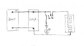
The venerable LM339 is good for such chores. While the output pull-up is lossy and uncertain, the pull-down is better, so I wired the module rail-to-output. HOWEVER I just saw that TI has downrated this part-series to 32V or less (it may take 36V, but they no longer test). Also the pull-down loss is low only to 10mA, rises rapidly at 20mA, so won't read right with a 25mA load.
So this won't work, but maybe someone else knows a part or a hack.
100k resistor adds a hint of hysteresis so it doesn't oscillate near threshold.
Attachments

1 - Would a regulator work - say a zener & pass transistor.
Below 30V, passes the full voltage; above 30V, regulates down to 30V?
2 - Does the battery voltage exceed 30V? Does the display only blow when charging? Could the display be switched out when charging?
Below 30V, passes the full voltage; above 30V, regulates down to 30V?
2 - Does the battery voltage exceed 30V? Does the display only blow when charging? Could the display be switched out when charging?
> say a zener & pass transistor.
It wants "NO" voltage drop at 25mA. The basic Resistor Zener Transistor will drop 0.6V to many V depending on load, also temperature.......
It wants "NO" voltage drop at 25mA. The basic Resistor Zener Transistor will drop 0.6V to many V depending on load, also temperature.......
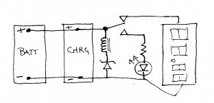
If the meter is in parallel with the charger and battery, what about a series string of zener, coil of NC relay, appropriate value resistor, and LED, also in parallel?
The relay contacts connect the V+ line to the display. If the voltage goes high the string conducts and the relay opens, cutting the voltage to the meter but the led comes on to tell you it's high but still charging. Would it work?
The relay contacts connect the V+ line to the display. If the voltage goes high the string conducts and the relay opens, cutting the voltage to the meter but the led comes on to tell you it's high but still charging. Would it work?
> say a zener & pass transistor.
It wants "NO" voltage drop at 25mA. The basic Resistor Zener Transistor will drop 0.6V to many V depending on load, also temperature.......
The load is the display so ~25ma.
It reads 0.6V low - so what? Do we need to know the exact battery voltage or just an indication of state of charge?
Reading up (as I didn't know much about this aspect of transistor behaviour) this would be the V sat value and could be as low as 0.1V and may rise to say 1V at higher current but the only load is a display that shouldn't deviate much in current draw.
Alternatively, have the charger power a relay that disconnects the display during charging. You would lose 0.7V of charging voltage at the battery due to blocking diode.
Well, I tried the circuit posted above and while the LED lights up the relay doesn't pull. So that's out.
Next, the circuit below, and as expected it works reliably. Problem is that the voltage window between pick-up and drop-out is about 3 volts. With 18V zener in series with a 12V Zettler coil it came on at 23V and dropped out at 20V. Too large to make it useful here.
I searched for coiled relays with a tighter on off window but didn't find anything. (Hard to search without a parameter expressly for that. . . . and searching by reading the on and off voltages in individual data sheets is too slow to be rewarding entertainment - though the spread in some was sort of amazing, 100 V on, 4V off!)
Solid state relays like this one look promising though. If it could work, the whole circuit can go on a small bit of perf-board to be tacked wherever convenient in the chassis.
Attachments
1 - Would a regulator work - say a zener & pass transistor.
Below 30V, passes the full voltage; above 30V, regulates down to 30V?
2 - Does the battery voltage exceed 30V? Does the display only blow when charging? Could the display be switched out when charging?
I have never seen the battery charge past 30V, probably thanks to the smart charger. The display doesn’t blow during the charge—it blows the first time it’s used after the charge. I don’t need the display to show exact voltage... I just need to know when it it getting below 24V, specifically never letting it get below 20V. Nor do I need actual digits displayed in the voltmeter, simple LED bulbs would suffice.
Actually, I should amend the last statement. Yes, the battery never charges over 30V. But the combination of the battery charged to 29V and the smart charger supplying its own voltage presumably goes over 30V.
What I need to do is make one of these things: 12 V BATTERY LEVEL INDICATOR [DIY] - YouTube
What I need to do is make one of these things: 12 V BATTERY LEVEL INDICATOR [DIY] - YouTube
Does anybody know how to adapt the schematic from the link above for more than 30V? My 24V battery charges up to 30V and then my charger adds some more voltage when connected.
There is a 339 /358 based charger circuit for 12 volts on the net, can be adapted for 24V easily, you can set start and stop charging with presets.
Charging a 24 V lead acid battery to 30+ is going to shorten its life.
There are modules to display line or DC volts powered off the battery, or use a simple truck voltmeter, or an analog one, can't be so expensive, and its input resistance is generally more than 1k, not much battery drain issue.
Something like this:
Automatic Battery Charger circuit using LM358 OP-AMP >> Power supplies
The battery is lithium ion. I already have a display manufactured by Sure. The problem is that it keeps blowing because the display is in the charge circuit and it can’t handle the extra voltage that the charger adds to the mix. So I have to disconnect the display every time I charge. I don’t want to have to do any disassembly to charge the battery.
Any of those designs from the YouTube video would be fine. In fact, simpler is preferred. But I need it to work for more than 30v.
Any of those designs from the YouTube video would be fine. In fact, simpler is preferred. But I need it to work for more than 30v.
- Home
- Design & Build
- Construction Tips
- Job Offer - Modding Display