I hope to build the entire circuit within a space of about 1 square inch, p2p. I was going to try with gate resistors no more than 10ohms and see what happens. The emitters of the VAS transistors also need a few ohms. Fortunately, source follower mosfets have appeared to be more stable to me than the common source configuration. I am only using one output pair which greatly reduces the chance of parasitic oscillations between mosfets.
Best regards

Best regards
subwo1 said:I am only using one output pair which greatly reduces the chance of parasitic oscillations between mosfets.
How do you figure that?
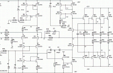
Charles Hansen said:I think the Ampzilla circuit is a variation on what Borbely called the "Lender circuit", where the emitter of the VAS is driven by one phase of the diff pair, while the other phase drives the base of the VAS. I can't see where the collector of what looks like an emitter follower is connected.
At any rate, adding an emitter follower to drive the base of the VAS will eliminate the slowdown from the Miller capacitance of the VAS. ....
The 2n5087 collector goes to a fixed reference, and is an emitter follower as you suggest. It's not the Lender VAS.
subwo1 said:I hope to build the entire circuit within a space of about 1 square inch, p2p. I was going to try with gate resistors no more than 10ohms and see what happens. The emitters of the VAS transistors also need a few ohms. Fortunately, source follower mosfets have appeared to be more stable to me than the common source configuration. I am only using one output pair which greatly reduces the chance of parasitic oscillations between mosfets.
Best regards
Even one MOSFET can oscillate by itself. The various capacitances and lead inductances form an efficient Colpitts oscillator, unless you are careful. Minimize lead length, use a .22mf bypass from drain to gnd per device, and terminate the gate drive with a moderately sized resistor, perhaps 100 ohm is as low as I would suggest. I even use shielded wire and ferrite beads if the output devices are off card.
This thing still has much more speed than you need for audio use, but it is a fun challenge to make it fast and stable.
About current mirror
Hi, Subwo1,
Want to ask about current mirror. There is a guy who said that this kind of current mirror is the "Rolls Royce" of current mirror. Is that ordinary current mirror that you use (and I use) is not good enough, so the sch has to stack 2 of them?
Hi, Subwo1,
Want to ask about current mirror. There is a guy who said that this kind of current mirror is the "Rolls Royce" of current mirror. Is that ordinary current mirror that you use (and I use) is not good enough, so the sch has to stack 2 of them?
Attachments
slowhands said:The 2n5087 collector goes to a fixed reference, and is an emitter follower as you suggest. It's not the Lender VAS.
Even one MOSFET can oscillate by itself.
Looking at the Ampzilla 2 schematic, it's not clear to me that the collector is going to a fixed point. It kind of looks like Bongiorno is using the signal on the collector to provide some sort of feedback to the current sources. The decoupling cap is only 0.1 uF, which is effective only above 400 Hz.
At any rate, this doesn't effect the forward signal path to the VAS. I still say that adding an emitter follower buffer on the base of the Lender circuit is just a variation on the Lender circuit. The base and emitter are being driven by opposite phases of the input differential circuit, which is the Lender circuit to me.
I agree that one MOSFET can oscillate by itself. I disagree that paralleling them makes things worse. Just give each device its own gate resistor, placed very close to the output device.
Re: About current mirror
This is a modification of a Wilson current mirror. A Wilson mirror uses feedback to attain higher accuracy of the "mirroring" action.
As with all things in audio, it's best to do some listening tests to decide what to use. Many times a simpler circuit will sound better.
Here is a link to a Japanese site that shows the modified Wilson current mirror. The text is a Babel translation and may not make good sense....
http://babelfish.altavista.com/babe...p/asahi/evo/amp/tech/current_mirror/index.htm
lumanauw said:There is a guy who said that this kind of current mirror is the "Rolls Royce" of current mirror. Is that ordinary current mirror that you use (and I use) is not good enough, so the sch has to stack 2 of them?
This is a modification of a Wilson current mirror. A Wilson mirror uses feedback to attain higher accuracy of the "mirroring" action.
As with all things in audio, it's best to do some listening tests to decide what to use. Many times a simpler circuit will sound better.
Here is a link to a Japanese site that shows the modified Wilson current mirror. The text is a Babel translation and may not make good sense....
http://babelfish.altavista.com/babe...p/asahi/evo/amp/tech/current_mirror/index.htm
Hi lumanauw,
It much closer to what has been suggested to lower distortion and unload the differential pair. I guess we may actually be seeking speed and simplicity with good but not the best attainable fidelity.
I did some simulation on both stacking current mirrors and also adding emitter follower buffers. I still like the original configuration more because it is more stable. Short signal path inside feedback loops seems to be key. One extra transistor in the signal path can push things over the edge. Integrated circuit op amps may suffer a similar trade-off, more gain stages tend to require that global negative feedback be less near the chip's upper frequency limits ??
I am redoubling efforts toward the goal Kal proposed: simplicity, speed and good sound. I am not sure very low measured distortion is presently the objective.
Hi slowhands,
Maybe if it works out, the circuit will be able to actively reject power supply ripple in a class H sub amp. But for more conventional use, the thinking is to have fidelity beyond the audio band in order to ensure that performance within the pass band is consistent.
Hi Charles,
After much work on SMPS design, I found that paralleling mosfets requires high gate resistors when they are being used in a standard totem pole. The signals otherwise feed between the mosfet gates on one end of the totem pole. For example, the upper mosfets can oscillate among themselves, in the way you mentioned, while the lower do the same, causing a short in usually one upper and one lower. I have blown about 100 mosfets trying to circumvent this problem. However, when only one set of mosfets is used, things seem to work fine.
I assume by "totem pole" you mean same-polarity devices driven by a push-pull signal? In my experience if I give each device its own gate resistor (placed very close to the device), there is no difference between single or paralleled device with regards to stability. (Of course, I could be wrong...🙂 )
In SMPS design the devices are usually the same polarity. But, the principle should still apply when paralleled devices at each power rail are opposite types, especially in common source configuration. Yet, for source followers, the stability and resistance to the destructive oscillation is greater because the unity gain tends to discourage the quick signal changes that trigger the oscillation somewhat. My thoughts on opposite polarity devices are conjecture as I have only paralleled same-type mosfets.🙂
Paralleling MOSFETS can cause them to behave like push-pull oscillators together with the parasitic elements. This is prevented by using gate resistors.
Regards
Charles
Regards
Charles
Some minimum value of gate resistors is usually needed. I have found among other things, that the lower the circuit voltage is, the less critical the gate resistor can become.
That's probably because the device capacitances significantly increase as the voltages are lowered. This will "slow things down" and help prevent oscillations. But I'm still wondering if you used individual gate resistors on each device when you paralleled them.
Good thought about the device capacitances, and another factor is that the available voltage swing in relation to the gates goes down.
Ahh, OK, that question is very good indeed. When I was trying to parallel N-ch mosfets in SMPS projects, each did have its own gate resistor. With voltage rails of +/- 160v I had determined that a 220 ohm gate resistor provided good protection for each IRF840, with a big loss of efficiency due to slow switching, however.
Ahh, OK, that question is very good indeed. When I was trying to parallel N-ch mosfets in SMPS projects, each did have its own gate resistor. With voltage rails of +/- 160v I had determined that a 220 ohm gate resistor provided good protection for each IRF840, with a big loss of efficiency due to slow switching, however.
Darlington after inputstage
Hi,
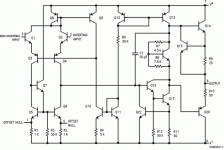
Actually I meant something like the 741 opamp, that is Q15 & Q17 in the schematic below. This time with the other polarities as in the Ampzilla detail.
The Lender like arrangement is used all the time by James Bongiorno. Charles mentioned a curious trick by James as the voltage dropped over the 3k9 resistor for the current source of the other input pair is used at the collector of the first transistor of the Darlington pair. In the Ampzilla II a 0.1µF/50V ceramic cap was used that ironically failed at the 53 V that was on it. In the Ampzilla IIa a 4.7µF cap was used.
Attachments
"As with all things in audio, it's best to do some listening tests to decide what to use. Many times a simpler circuit will sound better."
Or more/as likely the simpler circuit is functioning so well that it is indistingushable from "perfect". Or stated another way, reducing a vanishing small non-linearity results in an improvement that is vanishingly small regardless of how geat it may be in relation to the non-linearity.
I would conjecture that many of the improved current mirror schemes are to allow the use of poorly matched pairs in a high production volume, loww margin invironment. It is probably cheapper to add <$0.15 of materials cost than the additional labor it takes to do the matching. I'm not disparaging this - it simply makes economic sense.
.......but what about the JOB circuit? Anyone got a conceptual of the JOB circuit or a basic idea of it's topology.
Regards,
Jam
Regards,
Jam
Getting out of a FIYaudio jam.
No........ but you are just the man for the JOB. Go find it and stop wasting time posting so many cartoons. We all know you can do it!
No........ but you are just the man for the JOB. Go find it and stop wasting time posting so many cartoons. We all know you can do it!
It's not my JOB man........
Oh Yeah......... I forgot something..........
Sha na na na, sha na na na na na (bah-doo)
Sha na na na, sha na na na na na (bah-doo)
Sha na na na, sha na na na na na (bah-doo)
Sha na na na, sha na na na na na (bah)
Yip yip yip yip yip yip yip yip, mum um um um um um,
Get a JOB
Sha na na na, sha na na na na na
http://www.amazon.com/exec/obidos/clipserve/B00000091B001001/0/102-3779563-0888943
Attachments
Hi, all,
Is this all mean that for audio use, classical simple current mirror like Subwo1 use , consisting only 2 transistor, with bases attached to each other and attached to one of collector is good enough?
As with all things in audio, it's best to do some listening tests to decide what to use. Many times a simpler circuit will sound better.
I still like the original configuration more because it is more stable.
I would conjecture that many of the improved current mirror schemes are to allow the use of poorly matched pairs in a high production volume, loww margin invironment.
Is this all mean that for audio use, classical simple current mirror like Subwo1 use , consisting only 2 transistor, with bases attached to each other and attached to one of collector is good enough?
- Status
- Not open for further replies.
- Home
- Amplifiers
- Solid State
- JOB circuit by GOLDMUND


