I suggest you take a closer look at how I did the ES9022, as different from others.
Pictures of both sides of the PCB have been published, so it is not difficult to see.
http://www.diyaudio.com/forums/digi...ng-new-ess-vout-dac-es9022-2.html#post2458181
And you can try to mock up what I did with some SOIC16 adaptor boards, and a lot of P2P in air.
The same circuit done with different layout and different choice of components can sound totally different.
One of the guys who have my 9022 will testify to that, as he has heard two versions of 9022 done differently, with totally different results.
Patrick
Last edited:
question about filter
Patrick,
I just put together another ES9023 DAC (Subbu / JP board + their PS) and one of the JG filters from the group buy. It's still burning in but after running all night, it sounds quite promising. Thanks again for making the boards available.
I did have a question about the design. I notice that there are some small 10 ohm resistors at the power supply input - R7 and R8. Could you comment on the benefit of these vs. hooking up the filter directly to a well regulated power supply?
Thanks,
---Gary
Attachments
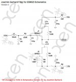
They help to isolate the left & right channel.
You can try to use 0R resistor or even wire jumper to see what you like better.
Patrick
You can try to use 0R resistor or even wire jumper to see what you like better.
Patrick
Patrick,
Thanks - that makes sense.
On another topic, can I ask about your user name - EUVL. Are you working on that the advanced litho technology that goes by that name?
Thanks - that makes sense.
On another topic, can I ask about your user name - EUVL. Are you working on that the advanced litho technology that goes by that name?
Progress update of 2nd GB.
Matching of BF862 and MMBFJ111 finished. Soldering will soon start. Hope I can deliver in April.
Thanks again for your patience.
WK
Matching of BF862 and MMBFJ111 finished. Soldering will soon start. Hope I can deliver in April.
Thanks again for your patience.
WK
The schematic says +- 15V... but I'd like to know myself whether there is a certain range for the supply.
Output voltage swing is about +/-3V.
Cascode voltage for the BF862 (Vds) is about 5V. Idss for the BF862 is 12~25mA.
The J111/J174 can take max 30V Vds, but dissipation is limited to around 250mW.
At below 5V Vds, capacitances for JFETs becomes too non-linear.
So you now have all information needed to calculate max/min rail voltages. 🙂
BTW all the above info can also be found in standard datasheets.
Patrick
Voltage range
The designer, and at least one other, has tested the filter buffer with 2 x 9V batteries
http://www.diyaudio.com/forums/digi...anybody-using-new-ess-vout-dac-es9022-44.html
The designer, and at least one other, has tested the filter buffer with 2 x 9V batteries
http://www.diyaudio.com/forums/digi...anybody-using-new-ess-vout-dac-es9022-44.html
They help to isolate the left & right channel.
You can try to use 0R resistor or even wire jumper to see what you like better.
Patrick,
I did the experiment of replacing the 10ohm resistors with wire jumpers and in my system, I think it's an improvement. It feels like the low end is a bit less confused in complex passages and the overall "ease of listening" improved somewhat. I think I'll keep it this way for a while.
---Gary
To get the best imaging, remove the 4x 10R resistors altogether.
Supply the left and right channel with totally separate low-impedance power supplies.
Ideally from batteries, or two separate transformers.
Patrick
Supply the left and right channel with totally separate low-impedance power supplies.
Ideally from batteries, or two separate transformers.
Patrick
Patrick/Joachim, how long will the batteries last when using them like in Joachim's setup (http://www.diyaudio.com/forums/digi...new-ess-vout-dac-es9022-44.html#post3092150)? Thanks.Supply the left and right channel with totally separate low-impedance power supplies.<br />
Ideally from batteries...
Depends on the batteries .
I use 280mA per hour accumulators. I think they are alkali-mangan.
Say we draw 10mA then they last 280 / 10 = 28 hours.
I would say 10 hours are safe.
I use 280mA per hour accumulators. I think they are alkali-mangan.
Say we draw 10mA then they last 280 / 10 = 28 hours.
I would say 10 hours are safe.
Here is an example :
ANS MAXE 9V-300 - ANSMANN maxe Akku, 9-Volt Block, 300mAh bei reichelt elektronik
There are cheeper ones.
ANS MAXE 9V-300 - ANSMANN maxe Akku, 9-Volt Block, 300mAh bei reichelt elektronik
There are cheeper ones.
I don't know much about audiophile battery technology, I keep a few of a type similar to the below link, around for LED Bike lighting:
3800mAh DC 12V Super Rechargeable Lithium ion Battery Energy Storage Pack | eBay
if one made a harness to reverse polarity on one of the feeds {not the battery harness, an intermediate harness to flip one source}... Then does one also need to NUL the circuit for any differences in the packs? Of course they both sag as they wear off the "just charged" "high". Pardon me for not having the schematic in front of me. I will be using mains power and regulators, just trying to help brain-storm the obvious questions.
The BF862 used in the circuit draws between 15 to 25mA.
Since there are 2 channels on one PCB, each PCB will draw about 50mA in total.
Unless of course you use separate batteries for left and right channel.
Patrick
Since there are 2 channels on one PCB, each PCB will draw about 50mA in total.
Unless of course you use separate batteries for left and right channel.
Patrick
Keep dac output caps when adding buffer?
I will be adding the buffer to a Subbu ES9023 dac, should I keep the output caps on the dac or should I remove them? Thanks.
I will be adding the buffer to a Subbu ES9023 dac, should I keep the output caps on the dac or should I remove them? Thanks.
There should be a 4.7n cap to Gnd at the output of the ES9022/23 DAC before the buffer.
Patrick
Patrick
- Home
- Group Buys
- Joachim Gerhard Filter Buffer for ES9022