Glad that you spotted the problem, no damage, and one more happy customer who actually did A-B test.
🙂
Patrick
🙂
Patrick
''Err, em. Fess up time. I had gnd and + output wrong way round on one channel.''
Hi Fran
Yup we all do stuff like that 🙂
Glad that you've had the chance to sort it out.😎
X2 on your assessment SQ wise
All good
Hi Fran
Yup we all do stuff like that 🙂
Glad that you've had the chance to sort it out.😎
X2 on your assessment SQ wise
All good
Yep. Its more apparent on some tracks than others. Listening for short bursts back and forth also makes it hard to pick up the differences. Listen for a few minutes though and every time you're switching back to the buffer.
Now I have to make the dac and filter into a new chassis, the plank-of-wood chassis ain't gonna work with mains voltages to the Tx!
Fran
Now I have to make the dac and filter into a new chassis, the plank-of-wood chassis ain't gonna work with mains voltages to the Tx!
Fran
I built a shunt to run my filter - but I'm curious: what is everyone else using?
Fran
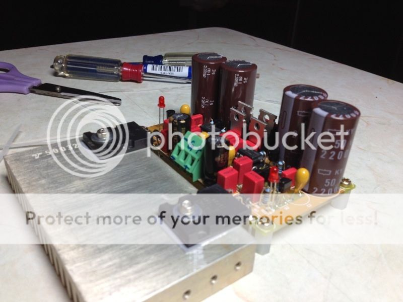
I am using this super reg to power the buffer.
Not a bit overkilled for consumption of less than 20mA ?
🙂
Patrick
That was for driving the op-amp IV originally and just handly to use it for the JG buffer.
I am using this super reg to power the buffer.
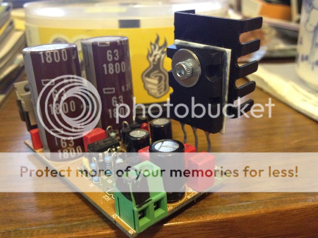
I also have one of those lying around. Does that regulator really need such a big heatsink?
Regards
I also have one of those lying around. Does that regulator really need such a big heatsink?
Regards
Not really, may be sufficient to just use one of this heat sink.
The active circuit is a cascoded JFET follower.
The follower JFET (BF862 upper) is cascoded and see a constant Vds pretty independent of output voltage.
The lower is a cascoded current source.
As such, the circuit has good PSRR.
For my "kitchen radio" (otherwise known as Sisters' Series), I just use 7815 / 7915.
For a slight upgrade a LT1763/LT1964 on 78xx/79xx pin compatible PCBs.
Or the XEN miniature Cap multiplier.
🙂
Even if you wish to use a shunt, your CCS current does not need to be more than 35mA.
A boostered TL431 would do.
Patrick
I just realised that the current values quoted in post #469, 470, & 476 were not well defined.
According to our record, the JFETs that Fran has have Idss of around 14mA.
So thet figure of 28mA he was referring to in post #469 was for one PCB, or two single-ended channels.
And I was misled by the phase he used "on each leg".
So the numbers I gave in post#470 and in #476 were for one channel.
Thus, for 2 single-ended channels, or one PCB, the max current consumption can be about 50mA.
If you then choose to use a shunt regulator, the current source should be delivering minimum 60mA.
(Some of you will of course argue that even 55mA is sufficient.) 😉
Sorry for causing any confusion,
Patrick
EUVL - you are 100% correct, that is for 2 channels. 28mA for each polarity.
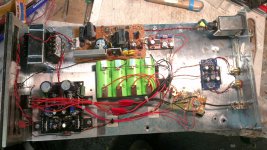
I thought I'd throw up a pic of my almost finished build. I'm using EUVLs 9022 dac (run on batteries) and the filter run from the salas shunt (the old hypnotise B1 boards butchered a bit). The other bits are for charging the batteries.
I had a bad mistake. When I reassembled everything I had no sound and DC offset from the DAC. I fried the 9022 - easier to do than you think with the batteries. After some advice and instructions from EUVL (thanks again!) I managed to remove the dead 9022 and replace it.
All is good, and I can tell you it sounds great with a shigaclone transport.
Fran
Attachments
- Home
- Group Buys
- Joachim Gerhard Filter Buffer for ES9022