I love TIG welding, it is amazing what you can do with stainless steel. During my professional career I have learned how great is stainless steel equipment.
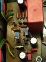
Placing of TO-3 on face-to-face aluminium angles is in theory simple but can be rather challenging. When you put two 4 mm angles face-to-face the hole for emitter and base leads is 8 mm long. Add to this thickness of the board and you end-up with leads almost too short. Almost, but still you may solder them.
Another challenge is insulation. I have used shrinking tubing on the leads and bolts to prevent contact with heat sink. Also, I have insulating bushings in all holes at the side in contact with the PCB.
Assembly is also tricky. Almost mission-impossible. Be patient and systematic. First put bushings in all holes on L profiles in contact with PCB. Then fix the PCB with two bolts so that the bushings do not fall from the holes. Mount transistors one-by-one. Do not forget to use mica washers and place transistor on the L profile so that the leads are in place, visible at the holes on the PCB. Then push the bolts through the holes and from the other side place the shrinking tubing into holes for bolts. Now you can fix the transistor with screw. Repeat the same procedure for all transistors and test if everything is isolated properly.
Thats all folks! 😎
Last edited:
It's not just the output transistors that get hot. Transformers, diode bridges, capacitance multiplier transistors are heated.
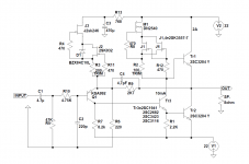
In my version of JLH2003 I use a TO3P case and my PCB. With fast transistors I have no problems and it sounds great.
I also upgraded both CCS with jfets and DN2540, and I did an extensive driver transistor test and found the best .
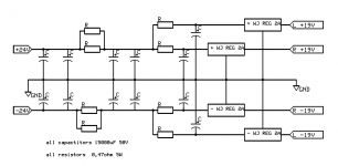
It has also been upgraded with 2A walt jung style superregulators for + and - supply.
https://www.diyaudio.com/forums/solid-state/3075-jlh-10-watt-class-amplifier-531.html#post5599887 from the first version onwards
I also upgraded both CCS with jfets and DN2540, and I did an extensive driver transistor test and found the best .
It has also been upgraded with 2A walt jung style superregulators for + and - supply.
https://www.diyaudio.com/forums/solid-state/3075-jlh-10-watt-class-amplifier-531.html#post5599887 from the first version onwards
Attachments

Thanks again for your previous very useful suggestions. Also this one has merit and it fits well into my recent decision to entirely re-think my design goals. First, I have decided to use mono-block-only design. I will keep just vertical position of the heat-sink to maintain natural convection. All other units may/will be re-located to maximize air-flow within the chassis. I will not refrain from using fans when natural convection fails to provide suitable cooling. One thing just remains top priority: adequate bias, at all costs.It's not just the output transistors that get hot. Transformers, diode bridges, capacitance multiplier transistors are heated.
Thanks
Yes, I've read your posts with utmost interest, especially in view of reduced choice of "antique" components. Your survey of alternative semiconductors has helped me to resolve many dilemmas and yet I had to order multiple transistors from different suppliers/producers. Unfortunately I wasn't systematic enough to make a record of all changes. Therefore I will sacrifice one pair of PCBs along with all components to identify which components fit well together. Do you have any fresh information on that subject.In my version of JLH2003 I use a TO3P case and my PCB. With fast transistors I have no problems and it sounds great.
I also upgraded both CCS with jfets and DN2540, and I did an extensive driver transistor test and found the best .
It has also been upgraded with 2A walt jung style superregulators for + and - supply.
I intend to try using Hifisonix Ripple-eater. I know you also have used capacitance multiplier. At present I use +/-18V toroidal transformer and I end up with a bit more than +/-24VDC. Capacitance multiplier (ripple eater) would result in optimal +/-22 VDC. Your thought on that subject?
And, by the way, haven't we met before in NO#1 flower shop headquarters? 😉

You can install an additional filter (passive or active) in the (+) rail between the collector of the output transistor and the driver resistor. This will reduce ripple and give a smooth start.
Gents, a very good option is the MJ802. They are 30 Amp 100 V devices and very rugged. Recommended by Geoff Moss himself, on TCAAS. I have used them for many years with no issue.
Sharing my experience building this a couple of times. My goal is to manage the heat from having the bias at 4A at dual 24VDC to drive Martin Logan ESL panels. I ended up using a rack mount industrial power supply that I retrofitted couple of quiet cooling fans with. I did remotely locate the supply using the sense lines. That removed a huge source of heat from the amp.
As far as power devices, I used TO3 devices I pulled from a couple of Krell amp boards, thinking they are sorted and matched. I used their OEM labeled MJ15024 and 2SC3281. Did not have issues with either type.
As far as power devices, I used TO3 devices I pulled from a couple of Krell amp boards, thinking they are sorted and matched. I used their OEM labeled MJ15024 and 2SC3281. Did not have issues with either type.
@ferret, @rss388
Thanks for useful information. Now I have first heard of possible use of MJ802. Perhaps I use it too for JLH2005, but I will certainly try it in Ripple Eater due to high Amperage and hFE value.
Have you measured bias current at individual transistors. I have used MJ15003 from two different producers: ON Semi and Inchange, for testing purposes only.
I have adjusted the bias current on CCS potentiometer and measured voltage across resistors. ON Semi transistors had currents equally distributed over individual devices. However, the Inchange devices had very uneven distribution ranging from 150 mA to 2000 mA. All other components were identical. This indicates that Inchange devices had very different hFE values and have been replaced with ON Semi devices.
Last edited:
@Berlusconi:
I think Krell sourced all their TO3 devices from Motorola/ON. The current distribution in either the MJ15024 and 484081 (Krell version of 2SC3281) types are quite even.
I did end up having to fan cool the amp itself. My heatsink was sized for 2A and +/- 19V but the amp clipped into the ESL so I bumped up the supply voltages and the bias current.
I love TIG welding, it is amazing what you can do with stainless steel. During my professional career I have learned how great is stainless steel equipment.
I can also use the TIG at the factory where I work and I like the result, but stainless steel is very hard to drill, I also have a folder and a cutter, I am in the food industry in the electrical maintenance section.
MJ8022 : 30A 100V hfe 25 - 100 Ib 7.5A 2Mhz
Mj15003: 20A 140V hfe 25- 150 Ib 5.0A 2Mhz
on paper, not much difference, you really have to compare them to listening.
#OldDIY
I will provide suction grilles coming from the bottom and on the top in the periphery of the vinyl turntable. I am not very good at drawing and it is not easy to be able to transcribe this on a single line. I will try to make a small plan of the whole. what I can say is when below the transformers there will be a wire mesh and the air will pass from below like a chimney and will come out on all 4 sides around the vinyl platinum support through grids.
there will be photos of the pre-assembly: the starting skeleton and then the final finish.
Phil
Indeed, stainless steel is apparently more difficult but the end product is rock solid, though heavier. Making threads into stainless steel is in my view much easier with professional tools and the resulting threads are indestructible, compared to aluminium and all these soft materials. Also drilling stainless steel with professional "Dormer" drill bits is so comfortable.I can also use the TIG at the factory where I work and I like the result, but stainless steel is very hard to drill, I also have a folder and a cutter, I am in the food industry in the electrical maintenance section.
MJ8022 : 30A 100V hfe 25 - 100 Ib 7.5A 2Mhz
Mj15003: 20A 140V hfe 25- 150 Ib 5.0A 2Mhz
on paper, not much difference, you really have to compare them to listening.
...
Phil
Now I am more concerned with adequate power supply: I have ordered Hifisonix ripple eater boards and plan to adapt them for this project because of their high ripple rejection. I want extract the maximum from this amplifier.
Of course, MJ8022 seems to be an attractive alternative even though I consider 22W of class A sound with my 97 dB speakers more than adequate for my purposes. I don't listen pop/rock at all.
Regards and pleasant working week 🙂
Yes, I've read your posts with utmost interest, especially in view of reduced choice of "antique" components. Your survey of alternative semiconductors has helped me to resolve many dilemmas and yet I had to order multiple transistors from different suppliers/producers. Unfortunately I wasn't systematic enough to make a record of all changes. Therefore I will sacrifice one pair of PCBs along with all components to identify which components fit well together. Do you have any fresh information on that subject.
I intend to try using Hifisonix Ripple-eater. I know you also have used capacitance multiplier. At present I use +/-18V toroidal transformer and I end up with a bit more than +/-24VDC. Capacitance multiplier (ripple eater) would result in optimal +/-22 VDC. Your thought on that subject?
😉
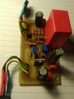
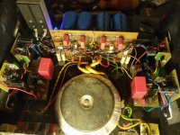
This weekend I brought my JLH back to life, the last six months in its place was Le Monstre.
Nothing has been done on it at the moment, but I recently upgraded the regulators while Le Monstre was still in the box.
The sound is great, beautiful .... Really great amp !!
But all this took time and effort to find the right combination of power supply and parts used in the amplifier.
Le Monstre is also a great amp, but JLH performs better at lower frequencies.
My recommendation is definitely a good regulator and before it as much as possible to reduce the ripple in the voltage, I got a great result with a CRCRC filter. I have about 2V voltage drop on the filter and another 3V on the regulator.
And, by the way, haven't we met before in NO#1 flower shop headquarters?😉
Who knows maybe we are 🙂
Attachments

- Home
- Amplifiers
- Solid State
- JLH2003