Hello
I have made many of these some years ago .. and have learnt very much by experimenting and seeing what other people have been doing. I thought I would dedicate this thread to some projects that I have in the pipe line for this amplifier. What has triggered this you may ask .. well I had a chance to listen to a couple of units that are still working and in fine fettle, and I was really impressed with the sound quality and the stability of the design and remembered how impressed I was when I first completed my first 2 units in the late 90's ....
so please enjoy and add your comments constructively .. 🙂
Also .. I have decided to make a test bench for the JLH fully regulated power supply that was used. I have used this with the maplin mosfet amplifier just as an example with very great results. You could use this as a stand alone module for other amplifiers and is fully adjustable within reason of course .. so pictures of the test bench as work in progress .. I will update through the construction phase
Attachments
Last edited:


JLH 80W MOSFET
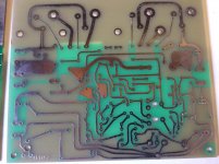
Hi Jamesfeline , I made this amp from a Williams hart kit nearly 20yrs ago. It
was fairly easy to construct, and it sounds smooth and very detailed.I have since learned there is a slight error in the earthing paths on the regulated pcb that has been mentioned on diyaudio forums. Basically it involves cutting a pcb track and connecting a wire link. All the best P M R🙂
Hello .. yes seen that thanks, many thanks for the info
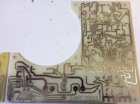
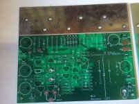
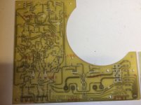
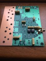
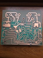
so, the boards shown in post 2 are your reproductions of the originals?
Hello ... these are the originals, but will make some gerber files later 😉
I purchased a full batch of PCB's from william Hart kits when they were still trading many years ago .. purchased all they had at the time
also I had permission from William Hart & JLH to make commercial units ( I have this in writing signed) but obviously never pursued this option
Last edited:
hello
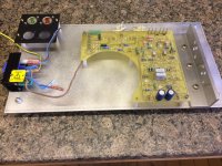
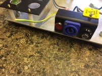
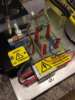
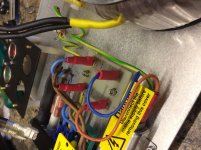
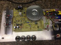
The mains supply has been completed and the transformer mounted (50v secondary's)
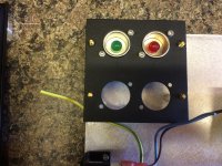
I also made a small PCB to make the main supply distribution easier to connect all the bit and bobs like mains filter / mains neon etc etc.
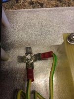
also one common earth point mounted on the main chassis
The mains supply has been completed and the transformer mounted (50v secondary's)
I also made a small PCB to make the main supply distribution easier to connect all the bit and bobs like mains filter / mains neon etc etc.
also one common earth point mounted on the main chassis
pictures .... in small batches as the server seems very slow
Attachments


Hello
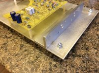
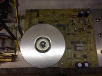
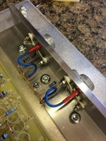
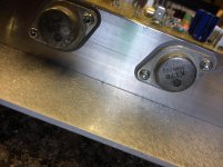
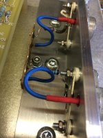
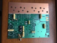
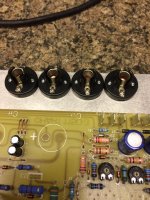
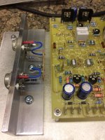
I have mounted the power transistors (mosfets) found a couple in my workshop doing nothing .. rare 2SK176 etc .
I was not happy with the sockets for these so modded a different way that I am happy with .. this way I can easily disconnect for replacement and modding
I have mounted the power transistors (mosfets) found a couple in my workshop doing nothing .. rare 2SK176 etc .
I was not happy with the sockets for these so modded a different way that I am happy with .. this way I can easily disconnect for replacement and modding
Attachments
That's a nice solution. But dosent go with the boards design stylistically. Would look much better visually if you had pertinax main boards ... or a full-on eyelet P2P build (not realistic I guess).
But I could see it work with the 1969 4-transistor amp if done all-P2P.
But I could see it work with the 1969 4-transistor amp if done all-P2P.
That's a nice solution. But dosent go with the boards design stylistically. Would look much better visually if you had pertinax main boards ... or a full-on eyelet P2P build (not realistic I guess).
But I could see it work with the 1969 4-transistor amp if done all-P2P.
hello ..
remember this is only for the power supply board not the power amplifier, I will post a separate pic once the power amplifier is completed
thanks for the comments .. also was thinking of doing P2P version, but might try a simpler design 1st
regards
Last edited:
Hello
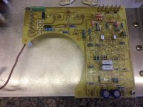
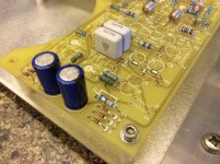
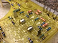
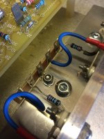
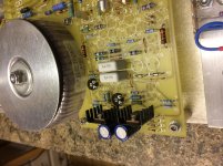
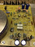
some more work complete ... more components installed and a couple of power supply transistors fitted and a trial fitment of the power supply capacitors ..
so just work in progress .. plus I have decided to use some filament lamps/bulbs as dummy loads as they are 5 w each
pictures attached in another post as the server is very slow


Enjoying this thread; I always lusted after building a JLH mosfet amp, but never could afford the Hart kit way back when.
I built both versions of JLH's 69 and 96 amps.
I built both versions of JLH's 69 and 96 amps.
- Home
- Amplifiers
- Solid State
- JLH Mosfet Power amplifier construction thread