Thanks
Hi Graham,
Thanks for your comments. I assume you meant R3 and not R8 in the schematic shown in post #8 of this thread? I will reduce the input resistor (R3) to 470R as suggested. I can see that this probably will help the high end response. After all, JLH added the input filter in 1996 to reduce the 3db point to 50kHz I believe. I actually wonder whether it is worth having an input filter at all?? What do you think?
Also, I am using a 470uF feedback cap, which currently is not bypassed by a poly cap. Should I do this? In addition, I'm wondering whether the feedback cap should be bipolar with this dual rail design?? The schematic shows it as polarised, but my limited understanding of the circuit suggests it could see reverse polarities??
Again, thanks for your comments.
Greg.
Hi Greg,
Guess I was not awake enough - some days I'm like this anyway, and I have to laugh about it and accept it instead of being concerned. Yes I meant post#8 when I wrote post#9 after rolling back to find the circuit.
I would recommend the 470 ohm series intput resistor to allow some RF input filtering with today's higher gain bandwidth product transistors. However, a new build using older device types might not need any input filtering.
Regarding the R8/R6 NFB divider of the post#8 circuit:
A reduction of values here to 1k and 82R will not alter forward amplification performance other than being better with say 1mF in place of your 470uF, but these values will double the potential damping factor and improve the signal to noise ratio by at least 3dB.
Your C4 is biased, so do not worry about using a quality electrolytic. If this were mine I would additionally parallel with say a good 22uF electrolytic and a 470nF polyester.
Hi Samuel,
My early GEMS did not have the local output stage NFB resistor fitted to the final design, and might not have had the hf phase shift minimising capacitors at the differential stage and mirror. These assist phase linear damping and control without relying solely upon full global NFB, and they could be fitted to other designs with advantage because they counter the inner loop phase shift so often caused by the value of C.dom at the VAS.
The sound ? I can only leave others to decide, but for me clean+clear, with sound depending on production source. Also, as far as bass slam is concerned - just watch out for your drivers because there is no weakness with regard to drive or control. Currrently my 100W-4R GEM (50W-8R) is driving 2x 4R drivers in parallel (=200W) without probs for a test loudspeaker.
Unfortunately the GEM amps really do show up bad CD productions, and independent auditions confirm the good amplification.
Cheers ......... Graham.
Ok, thanks Graham. So in summary:
1) Leave input filter in place with 47k resistor (R2) and 330pF cap (C2), but replace R3 with 470R.
2) Replace R8 with 1k, and R6 with 82R.
3) Replace C4 with 1000uF, bypassed with 22uF and 0.47uF
Ok think I've got it. Will give this a go. Off to make some new boards...
My C4 is currently a 470uF low esr electrolytic not bypassed. The amp has very good midrange but the treble is a bit lacking. Hopefully your improvements will help. I have read that 1000uF is a bit large for this cap (on the class a website), but I think it might be ok if done as you mentioned - the website did not mention any modification to the resistor values or double bypassing of the cap.
Cheers,
Greg.
Hi Greg,
Yes to your 1-2-3.
But can I suggest that you actually try mods 1 and 2 only and listen to the results on one channel before going to the trouble of making new boards.
I suggest you test without changing your 470uF because the difference at LF due to this alone will be slight, and then only add the increased value with parallel components if you feel the other mods worthwhile.
Yes some people would consider the 1mF unnecessarily large without changing the standard JLH 220 ohm resistor. Maybe those who tried it did not guard against electrolytic characteristics !
I parallel all PSU (and bootstrap) electrolytics too because an impedance peak on low impedance circuitry can lead to instability or common mode distortion.
Cheers ........... Graham.
The pursuit of happiness
Hi Graham,
I just tried some of your mods RE the input filter and bypass cap. For the bypass cap, I simply put a 1uF poly cap in parallel with the 470uF feedback cap. It is quite obvious that the treble response has improved dramatically, but now I don't actually like the sound. There's almost too much treble, and a big bit missing in the high-mid range.
I realise that adding the 22uF cap in addition will probably fix this flat spot. To do this, I think I would want to make the changes to R6/R8 that you mentioned, as I'm hesitant to make the overall capacitance much bigger with the current resistor values.
Would you mind explaining how this part of the circuit works and what effect changing these resistors (one or other, or both) has, eg to overall feedback values, frequency response and so on. I really don't know mcuh about it.
Your advice is most appreciated.
Cheers,
Greg.
Hi Greg,
The pursuit of happiness ?
There is much more within AF than many folks get to hear.
When you start removing NFB losses due to the decoupling electrolytic you need to start looking out for other things too.
Get used to this for a few days and go back to the way it was and you'll miss the detail.
Your equipment, layout and LS obviously were more relaxed to listen to before, and there is nothing wrong with that. To claim that or this is more correct is thus quite wrong.
Maybe your LS/leads suited the original arrangement; maybe changes here will make for further improvement, though whether you would like it I cannot say.
However, I don't see how an unparalleled single electrolytic can be rigth within a NFB loop, because any error developed by it is multiplied by the divider ratio wrt input at appears at output; this includes degraded control capabilities which can affect tonality and soften detail.
It is very unlikely that you now have anything missing which you had before, just the flatness of your response has been extended so it sounds different.
Any electrolytic used for NFB needs to be an excellent quality low ESR type, and these are much more expensive than your average radial.
Cheers ......... Graham.
Jlh
Hi all,
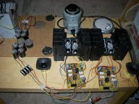
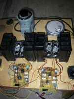
I know this is old thread, but I do have a question about JLH amplifier. I was cleaning the basement and found quite a lot of heatsinks as well as output transistors. So I decided to built JLH classA amp. Probably 20 watts version with double the output transistors.
However, I found lots of pnp MJ15004 original ON transistors. No npn. Questions is, how should I modify the circuit to use pnp. I do not want to make a mistake, hence the question.
Is it just a simple replace all the npn with pnp transistors and flip the supply polarity and electrolytics, or are the bigger changes needed?
Thanks,
ed
Hi all,
I know this is old thread, but I do have a question about JLH amplifier. I was cleaning the basement and found quite a lot of heatsinks as well as output transistors. So I decided to built JLH classA amp. Probably 20 watts version with double the output transistors.
However, I found lots of pnp MJ15004 original ON transistors. No npn. Questions is, how should I modify the circuit to use pnp. I do not want to make a mistake, hence the question.
Is it just a simple replace all the npn with pnp transistors and flip the supply polarity and electrolytics, or are the bigger changes needed?
Thanks,
ed
Attachments
Yep...flip the supply polarity, invert condensers and replace NPN by PNP and the
opposite... i think will work this way... i have tried into some amplifiers and they have operated.
Diodes must be inverted too.
regards,
Carlos
opposite... i think will work this way... i have tried into some amplifiers and they have operated.
Diodes must be inverted too.
regards,
Carlos
Re: Jlh
I've flipped the schematic for a headphone amplifier, and it runs unproblematic. If you're up to some tweaks, it sounds better with differential input (without current mirror), and even better with complementary feedback pair in the diff input stage.adason said:Hi all,
I know this is old thread, but I do have a question about JLH amplifier. I was cleaning the basement and found quite a lot of heatsinks as well as output transistors. So I decided to built JLH classA amp. Probably 20 watts version with double the output transistors.
However, I found lots of pnp MJ15004 original ON transistors. No npn. Questions is, how should I modify the circuit to use pnp. I do not want to make a mistake, hence the question.
Is it just a simple replace all the npn with pnp transistors and flip the supply polarity and electrolytics, or are the bigger changes needed?
Thanks,
ed
Hi destroyer X and nelsonvandal,
thanks for reasurance. Sounds good.
I am off to making the boards.
ed
thanks for reasurance. Sounds good.
I am off to making the boards.
ed
Yes I'm very sure. No need to do any measurements or think twice. The sound is simply better, and by better I mean less coloration. If you like an uncolored sound or not is another story. With single transistor input, the sound is fuller/warmer but this is a coloration. I think it's due to high second order distortion, but I'm not sure since I don't have equipment to measure it. You're next question will be "how do I know". I compare it to nothing, insert it in the signal path behind another amp.Lumba Ogir said:Nelson,
Are you really sure?
Nelson,
I always listen to your exceedingly accurate and tasteful subjective judgment very carefully, but our reasoning and approach is different. The single-ended input is the only explanation for the appealing sound of many British-style amplifiers, a substantial advantage over the push-pull mode in particular, where the signal is harmfully amplified by two (different) devices with some measure of overlap, producing disagreeable distortions and a significantly less favorable harmonic spectrum. At some point, you might find it necessary to reassess your stance.
I always listen to your exceedingly accurate and tasteful subjective judgment very carefully, but our reasoning and approach is different. The single-ended input is the only explanation for the appealing sound of many British-style amplifiers, a substantial advantage over the push-pull mode in particular, where the signal is harmfully amplified by two (different) devices with some measure of overlap, producing disagreeable distortions and a significantly less favorable harmonic spectrum. At some point, you might find it necessary to reassess your stance.
hi destroyer X and nelsonvandal,
Success! I just finished and briefly tested the JLH 25 watt version as I mentioned, with four MJ15004 per side. Works from the first moment without any problem. So far tested only with spare diposable speakers before I will finish speaker delay and dc protestion circuit. I have ordered it from valleman. Then I will test the sound on good speakers.
Thanks,
ed
- Status
- Not open for further replies.
- Home
- Amplifiers
- Solid State
- JLH class A or penultimate zen for driving low sensitivity speakers?