Helllo all,
I'm contemplating constructing either a penultimate zen or JLH class a amp, and from what I've read, it sounds like I would be pretty happy with either (though if anyone has a strong opinion of why one is better then the other I would like to hear it) . My question is which one would sound better with relatively generic, low sensitivity speakers? It seems that this "audiophile quality" amp can be made with a poor person's budget, but the high quality speakers are still out of reach.
Your advice is appreciated,
Greg.
Well, I'm building a JLH now, and so I'm biased toward it. But cost wise, these are not cheap to build. Sure, you can add up the pcb component prices and come to just a few pounds. However, the reservoir electrolytics, output devices, heatsinks and PSU transformers can cost you a small fortune.
(My design is in fact a colaborative project called the JLH-2005, which updates the original JLH to use more modern parts and tecniques. We will publish the schematic and PCB layout once I have tested it!)
(My design is in fact a colaborative project called the JLH-2005, which updates the original JLH to use more modern parts and tecniques. We will publish the schematic and PCB layout once I have tested it!)
Hi,
As stated its the cost of the hardware that decides the budget.
Single ended, or the option of, requires lots of heatsinking.
Other choices are Elliot's "Death of Zen" and Pass's PLH (JLH-u-like).
Suitable speakers would use a highish sensitivity 8" (smaller drivers
generally
do not hit the sensitivity with decent bass) +1" dome in a largish vented box.
Such drivers are getting rarer .....
🙂/sreten.
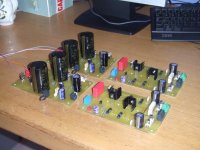
Attached are first photos of the nearly completed JLH-2005 pcbs. The off-board power transistors are not connected yet, but it's getting there!
The JLH-2005 is an implementation of John Linsley-Hood's famous Class-A amplifer, using modern parts.
The JLH-2005 is an implementation of John Linsley-Hood's famous Class-A amplifer, using modern parts.
Attachments
As nice as both those designs are, it is possible that you
will want more muscle than they provide. I would guess the
tipping point is probably about 88-90 dB/watt or more sensitivity
in your drivers.
😎
will want more muscle than they provide. I would guess the
tipping point is probably about 88-90 dB/watt or more sensitivity
in your drivers.
😎
Update
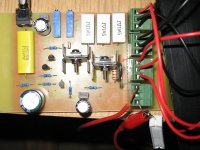
Well last night I finally lashed together my +/-22v dual rail JLH 2000 prototype, as shown in the photos (same as 1996 version but with constant current sources). The entire thing (minus power supply and output transistors) fits on a 3 x 3.5" PCB. You'll notice the 330pF input filer cap is missing as I didn't have one handy, but will add it soon. It uses generic transistors and capacitors throughout, and CCSs for the input and output transistors, as suggested by fellow forum members. The CCS/input transistors are BC560s, and BC560/BD140 + BD139 for the output stage. It worked right first time. How does it sound? Well, this is my first homebuilt amp, and I was a little sceptical of all you audiophiles with your transparency, authority, soundstage, etc mumbo jumbo. I was a bit scared I'd turn it on and think it was all a waste of time and no better than my pioneer home theatre amp, but I have to say it sounds unbelievable! It brings out parts of the music I never knew were there, like the little scratches of the guitarist's hands on the frets and imperfections in the singer's voice. Ok, I'm no audiophile, but it sounds better than any amp I have heard in a shop. I replayed the songs on my other amp and realised the sounds are there, but this amp actually makes you notice them. They don’t fall into the blur of the music. I can't wait to make a proper power supply and housing. Also, the 10-15 watt is more than adequate for "reasonable" listening levels, even with my insensitive home theatre speakers. Highly recommended to anyone.
Well last night I finally lashed together my +/-22v dual rail JLH 2000 prototype, as shown in the photos (same as 1996 version but with constant current sources). The entire thing (minus power supply and output transistors) fits on a 3 x 3.5" PCB. You'll notice the 330pF input filer cap is missing as I didn't have one handy, but will add it soon. It uses generic transistors and capacitors throughout, and CCSs for the input and output transistors, as suggested by fellow forum members. The CCS/input transistors are BC560s, and BC560/BD140 + BD139 for the output stage. It worked right first time. How does it sound? Well, this is my first homebuilt amp, and I was a little sceptical of all you audiophiles with your transparency, authority, soundstage, etc mumbo jumbo. I was a bit scared I'd turn it on and think it was all a waste of time and no better than my pioneer home theatre amp, but I have to say it sounds unbelievable! It brings out parts of the music I never knew were there, like the little scratches of the guitarist's hands on the frets and imperfections in the singer's voice. Ok, I'm no audiophile, but it sounds better than any amp I have heard in a shop. I replayed the songs on my other amp and realised the sounds are there, but this amp actually makes you notice them. They don’t fall into the blur of the music. I can't wait to make a proper power supply and housing. Also, the 10-15 watt is more than adequate for "reasonable" listening levels, even with my insensitive home theatre speakers. Highly recommended to anyone.
Attachments
updated jlh amp
I'm very interested in your updated version... And look forward to seeing a published pcb . I built a version some yrs. ago and was impressed. Thanks-
I'm very interested in your updated version... And look forward to seeing a published pcb . I built a version some yrs. ago and was impressed. Thanks-
Schematic
I used this schematic from the class-A amplifier site, except I changed the 2SA970s for BC560s, the 2SA1358 for BD140, and the 2SC3421 for a BD139, selected for high gain using a cheap multimeter transistor tester. Power supply caps aside, I spent probably $AUD20, ($US13) on the whole thing. It really does sound very good. I'll email you the board design if you like. It's my first ever PCB, so the layout may leave a bit to be desired.
I used this schematic from the class-A amplifier site, except I changed the 2SA970s for BC560s, the 2SA1358 for BD140, and the 2SC3421 for a BD139, selected for high gain using a cheap multimeter transistor tester. Power supply caps aside, I spent probably $AUD20, ($US13) on the whole thing. It really does sound very good. I'll email you the board design if you like. It's my first ever PCB, so the layout may leave a bit to be desired.
Attachments

JLH design
Hi greg, I'd appreciate your pcb design. I've already built the power supply , still functional but (currently) 'unemployed' (like myself... so... I've time on my hands and need new project. It looks good. Thanks- (am working on wifes computer) ..hmmm which begs question, can you (at other end) see my e-mail? If not, let me know.
Hi greg, I'd appreciate your pcb design. I've already built the power supply , still functional but (currently) 'unemployed' (like myself... so... I've time on my hands and need new project. It looks good. Thanks- (am working on wifes computer) ..hmmm which begs question, can you (at other end) see my e-mail? If not, let me know.
Re: Update
Congratulations.
😎
gregjpeters said:Well, this is my first homebuilt amp, and I was a little sceptical of all you audiophiles with your transparency, authority, soundstage, etc mumbo jumbo. I was a bit scared I'd turn it on and think it was all a waste of time and no better than my pioneer home theatre amp, but I have to say it sounds unbelievable! It brings out parts of the music I never knew were there, like the little scratches of the guitarist's hands on the frets and imperfections in the singer's voice
Congratulations.
😎
I bet you would be itching to build the full blown version of Geoff's website (with 2SA970, etc.) within 6 months.
I did (with 8 output devices), and never regreted.
🙂
Patrick
PS But then I admitted have not tried Graham Maynard's GEM.
I did (with 8 output devices), and never regreted.
🙂
Patrick
PS But then I admitted have not tried Graham Maynard's GEM.
In my case, JLH sounds better. More transparent and cleaner than Zen/Aleph. But it only my subjective opinion 😉 My speakers have only -88dB sensitivity.
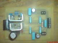
This is old photo one of my first JLH-2005 PCB (outputs don't installed yet). Gain selected MJL21194s on output.
This is old photo one of my first JLH-2005 PCB (outputs don't installed yet). Gain selected MJL21194s on output.
Attachments
> In my case, JLH sounds better. More transparent and cleaner than Zen/Aleph. But it only my subjective opinion.
I would echo that.
Patrick
I would echo that.
Patrick
FaTTy said:In my case, JLH sounds better. More transparent and cleaner than Zen/Aleph.
Again we go back to the argument which subjectively sounds better...PP or SE? 2nd H or 3H?
Try NP's adjustable PLH😀
It is the short NFB path of the JLH which makes it such a clean performer. This being one common base stage wrt input (low phase shift) followed by the composite common emitter output stage wrt ground.
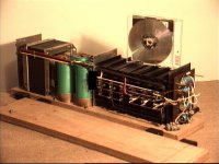
My own 100W JHL some 35yrs ago dissipated 300W via transistors directly bolted to insulated heatsinks. It is 2ft long and the heatsinks induced convection cooling.
This monster still works, though it became a test-bed for checking possible upgrades, none of which worked better in genuine class-A.
Geoff's excellent Class-A website is at;-
http://www.tcaas.btinternet.co.uk/index.htm
Cheers ........ Graham
Attachments
A quick question
Hi All,
Thanks for your positive feedback, pardon the pun.
Just quickly, I'm yet to attach the 330pF input filter capacitor, and was wondering if there is any problem with using a ceramic cap for this purpose? 330pF plastic caps aren't that common.
Thanks again,
Greg.
Hi All,
Thanks for your positive feedback, pardon the pun.
Just quickly, I'm yet to attach the 330pF input filter capacitor, and was wondering if there is any problem with using a ceramic cap for this purpose? 330pF plastic caps aren't that common.
Thanks again,
Greg.
Graham, why don't you tell us about the sound of your modified JLH, one version which is 50watts and the other full blown version of 100watts in comparison with the 1969 and 1996 versions of the original JLH and with the latest updates on Geoff's website.
Graham Maynard
Wow, 100W JLH... you are maniac 🙂 Nice way to get warm in the winter 🙂
gregjpeters
Polypropylene or polystyrene caps are recomended here. Ceramic ones may get sound suffer. But no a big deal to order something like Wima FKP-2 i think.
I use them.
Wow, 100W JLH... you are maniac 🙂 Nice way to get warm in the winter 🙂
gregjpeters
Polypropylene or polystyrene caps are recomended here. Ceramic ones may get sound suffer. But no a big deal to order something like Wima FKP-2 i think.
I use them.
Hi Greg,
By all means fit ceramic in this low voltage slewing position. It will work well until you can find the correct component type.
Also if your other equipment is good I would recommend using the higher capacitor values shown in Post#9.
You could also try reducing R3 to 470R. You might not hear any difference on most reproduction, but that 4k7 is in series with the common base NFB input sensing reference (input), and can lead to sibilance, transients, cymball, trumpet sounds etc. becoming fractionally dulled.
Hi Samuel,
I used higher value 'C's than JLH, and had minimum input filtering with low impedance line drive from the outset.
100W of JLH pure class-A can sound remarkably clean, but does not have the same dynamic headroom and bass driver control as would say 100W of early Nelson Pass class-A, or 100W SS class-AB or good 100W tube, but then you would not be aware of this lack ( and might find it hard to believe ) unless you had two amps side-by-side for direct comparison when playing loudly.
I did not like the idea of further reducing the maximum output by using the Q7/8 current source so chose to not use it.
I am not sure which 50W and 100W 'modified JLH' circuits you refer to.
Hi FaTTy,
Exactly !!! And it was much hotter than a Leak TL50+ which would play equally loud before distorting due to the way in which (new) tubes with their broad transformer coupled impedance matching capabilities are not similarly peak current limited when compared to fixed JLH base bias.
Cheers ....... Graham.
This http://gmweb2.net/Diagrams/GEM/GEM100ccs.gif is the 50watt and this http://gmweb2.net/Diagrams/GEM/GEM200.gif is the 100watt amps that I referred to.
It is interesting that you mention now about the slightly laid back slam and lesser bass control because this is what I reported as my observations in the original GEM thread. I had made direct comparisons with my Giovanno Stochino amp.
It is interesting that you mention now about the slightly laid back slam and lesser bass control because this is what I reported as my observations in the original GEM thread. I had made direct comparisons with my Giovanno Stochino amp.
- Status
- Not open for further replies.
- Home
- Amplifiers
- Solid State
- JLH class A or penultimate zen for driving low sensitivity speakers?