JHL Class A headphone amplifier pre-amp kit diy JLH AMP | eBay
I purchased this kit for about $20 with shipping and all, just now got around to putting it together. It came without any build instructions and attempts to contact the seller have left me empty handed for answers.
As you will notice on the pictures it has a VR on each channel...i assume for setting bias or output or something...i have requested instruction on how to set this amp up regarding this VR but again, no response...
If anyone can tell me how to make the appropriate adjustments on this amp I would be greatly appreciative of your assistance.
Thanks in advance!
The trimmers are likely for biasing the output transistors. Turn the board over and measure the resistance of each with your DMM. There is probably a sweet spot, but without more information I would just make them both equal in the middle of the range. If the trimmer is 100 ohms, for example, set them both to 50.
When you power up, you need to measure the current on each channel. Without a schematic, it's impossible to say where. This is often done by measuring voltage across a resistor and using Ohm's Law to get current. You will need two DMMs to balance the channels, each measuring voltage (current) on one of the channels. Once the amp has warmed up, you can start tweaking the trimmers. Usually one side will run a bit "hotter" than the other. If the output transistors are on the same heatsink, they will better share the excess heat and stabilize easier.
You want to make sure the transistors equalize at a reasonable quiescent current, certainly no more than 2A. If there is too much power applied or the bias is too high, you can get thermal runaway. You might try the Class A Website for info on this amp.
Again, a schematic would be helpful, as well as some information about your power supply.
I buy kits from a few Ebay vendors and don't have the problems with schematics. These days, most arrive as attachments to the invoice and only a few dispatch with the kit. Leading sellers now post them in their full website descriptions so why not look at the sites of the bigger names, since these guys usually sell the same boards or even whole kits as everyone else. Look on the board to see who designed it, as guys like LJM are members here so ask around.
The Class-A Amplifier Site - JLH Headphone Amplifiers
Believe it or not, first I found this article above and then five minutes later the seller sent me a message confirming what the article states close to the end...it is to adjust DC offset to as cose to zero as possible...
This guy at eBay seems to be a new seller, i too buy lots of these types of kits and generally have no issues receiving detailed instructions...he doesnt appear to have a website like some of the others.
Thanks again!
sorry to revive the old thread...
I too have bought the same headphone amp, just out of curiosity, and after assembly I am having some difficulties.
When I put 15-0-15 ac on it, it starts smoking. At closer inspection, the resistors R1 and R2 feeding the output transistor heats up too much. I used variac to power it slowly, and it can be had at 4-0-4 ac with those resistors warm. However, I do not know what else to do, there is not bias adjustment, and all the parts seems ok and in correct place, checked it twice...
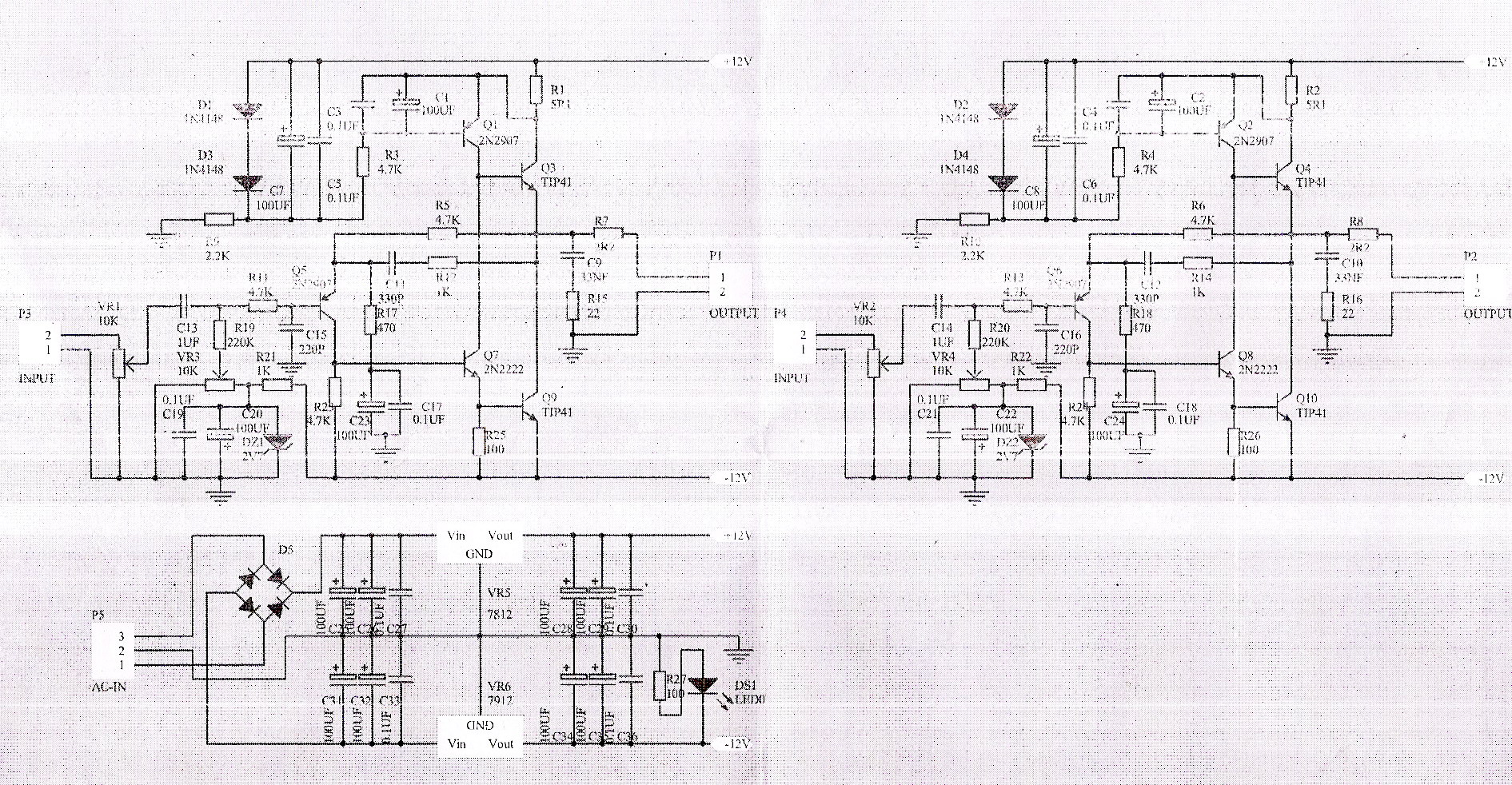
Any suggestions what shuld I do to make it work? Should I use higher wattage resistor? Or lower resitance? The output transistors do not get hot, only those 5 ohm resistors. I attached schematics. Any suggestions? Thanks, ed
I too have bought the same headphone amp, just out of curiosity, and after assembly I am having some difficulties.
When I put 15-0-15 ac on it, it starts smoking. At closer inspection, the resistors R1 and R2 feeding the output transistor heats up too much. I used variac to power it slowly, and it can be had at 4-0-4 ac with those resistors warm. However, I do not know what else to do, there is not bias adjustment, and all the parts seems ok and in correct place, checked it twice...
Any suggestions what shuld I do to make it work? Should I use higher wattage resistor? Or lower resitance? The output transistors do not get hot, only those 5 ohm resistors. I attached schematics. Any suggestions? Thanks, ed
Attachments

Last edited:
anyone?
Reviving a dormant dead end here. I just put this same amp together this morning. Parts were all there nothing missing. Went together very nicely and easily.
Once finished I wondered how to set the bias/offset and did a search to find this thread. I was also very skeptical of their choice of a 1/4w 5.1ohm resistor for the main class A current loop. Reading your experience with smoke urged me to swap out with two 2.2ohm X 2watt resistors in series. I grounded the inputs and applied +/-15vac from a transformer. No smoke and nothing burning and voltage across 4.4ohm now reads 0.615v. That's about 140mA quiescent current. I think that sounds about right? But have no idea. There are other threads that discuss this amp. My amp has the same exact schematic posted here though.
I will test it with a 91dB Faital Pro 3FE22 driver with maybe an extra series resistor next to make sure I don't blow headphones.
Need to adjust either offset or bias with the 10k trim pots.
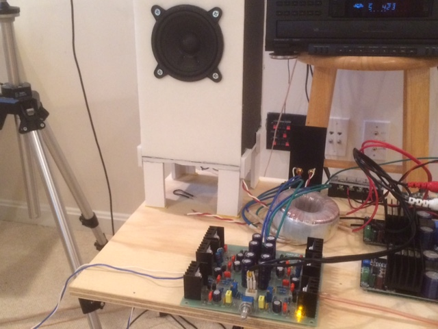
I just adjusted the trimpots for zero offset - seems stable. I just hooked up my 8ohm speaker directly to it and played music from my CD player. Surprisingly, it can drive speakers pretty loudly - I am ashamed to admit maybe at 1/2 volume that my ACA can do without a pre-amp. Hmm... not a bad class A preamp, headamp, or regular fleawatt amp at all. Sounds very nice. 😀
I am going to see if I have a long term stability issue with zero offset. Heatsinks are not too hot - I can touch them for 10 seconds without having to pull my fingers away.
Amp ordered here:
http://www.aliexpress.com/item/JHL-Class-A-Headphone-amplifier-PRE-AMP-KIT-DIY/553648524.html
Powering 3FE22 bass reflex speaker:
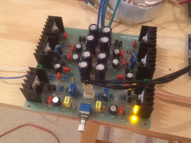
Closeup:
I am going to see if I have a long term stability issue with zero offset. Heatsinks are not too hot - I can touch them for 10 seconds without having to pull my fingers away.
Amp ordered here:
http://www.aliexpress.com/item/JHL-Class-A-Headphone-amplifier-PRE-AMP-KIT-DIY/553648524.html
Powering 3FE22 bass reflex speaker:
Closeup:
Attachments

Last edited:
You're looking at about 1.6 W into 8 ohms there, that's not nothing - back in the '70s, a larger portable radio would deliver about as much. Your speakers seem to be decently efficient to boot, going by 3FE22 data. Even with a minimum impedance of 6.7 ohms, you should always be getting out about 1.3 watts per channel, for a peak amplitude of at least 90 dB and change, plus 3 dB since you've got two channels. That would seem generally adequate for my needs at least.
BTW, I do think the quarter watt job would be just fine for the 5.1R registor. If you do the math, at 120 mA it'll dissipate about 70 mW and change, still less than a third of its nominal rating (which would be a good rule of thumb for sizing). If it does go up in smoke, something is clearly wrong, and in such cases I'd rather have a cheap resistor die than something more important.
BTW, I do think the quarter watt job would be just fine for the 5.1R registor. If you do the math, at 120 mA it'll dissipate about 70 mW and change, still less than a third of its nominal rating (which would be a good rule of thumb for sizing). If it does go up in smoke, something is clearly wrong, and in such cases I'd rather have a cheap resistor die than something more important.
I just hooked up a 3.5mm headphone jack and went direct drive (no output caps - felt like living dangerously). I have Sony MDR-V6's and thought I knew what they should sound like. Wow! Never heard such detail and resolution before. And the bass dogs deep. Nice. 🙂
The gain is a bit high as I am barely cracking the volume knob open. MDRV6's are decent sensitivity.
I am using a cheap DAC with digital coax from CD player and then RCA outs to amp.
Still amazed at the sound.
This is a great deal for someone wishing to get into class A for cheap.
The gain is a bit high as I am barely cracking the volume knob open. MDRV6's are decent sensitivity.
I am using a cheap DAC with digital coax from CD player and then RCA outs to amp.
Still amazed at the sound.
This is a great deal for someone wishing to get into class A for cheap.
Last edited:
The gain is a bit high as I am barely cracking the volume knob open.
Any idea which 2 resistors would need to be changed to lower the gain?
Do you have a schematic you can post?
Thanks...
Mine is same as in post 5. In the other thread - someone suggested a different resistor that changes the gain. You will have to read it because the boards are made by different vendors and labels are not all the same.
http://www.diyaudio.com/forums/headphone-systems/159202-jlh-headphone-amp.html
I think one member said it is R5 (the feedback resistor) and changing that to about 2k from 4.7k lowers the gain. Seems to make sense as gain in an op amp is Rf/Ri.
http://www.diyaudio.com/forums/headphone-systems/159202-jlh-headphone-amp.html
I think one member said it is R5 (the feedback resistor) and changing that to about 2k from 4.7k lowers the gain. Seems to make sense as gain in an op amp is Rf/Ri.
Last edited:
In this schematic, Ashok states that the gain is is R13/R8+1.
http://www.diyaudio.com/forums/headphone-systems/159202-jlh-headphone-amp-2.html#post2074455
So you think its R5/R17+1 for the circuit you posted?
That would be a gain of 5.68 if you change R5 to 2.2K...still a little high for me.
I don't like high-gain circuits, especially with inexpensive volume pots, because you're usually in the pot's region where channel imbalance is the highest.
Changing R17 to 1K and R5 to 2.2K should result in a gain of 3.2.
I wonder if the lower gain would affect stability?
This is indeed a nice preamp/headphone amp/small amp. The issue with mine, its been few years, as I recall, was one faulty output transistor. It was shorted. Replacing it fixed the problem. Running too hot and output ofset drift is a problem, because heatsinks are inadequate. Since the first one I built the same kit with bigger heatsinks, I feel much safer to use it. While the sound of this circuit is very good, there are better sounding circuits. I have Musical Fidelity V1 tube headphone amp, which is great, recently spent lots of time with old SE Magnavox tube 6EU7/6BQ5 amp. Equaly low in power, ~2 watts, so it can serve as headphone amp and small amp for desktop speakers. Sounds sweeter than JLH. Even LM1875 can make great sounding headphone amp.
Original eBay kit has C23/C24 drawn in wrong polarity.
Original eBay kit has C23/C24 drawn in wrong polarity.
Even a LM1875 can make great sounding headphone amp.
Horrors! not an integrated circuit chip thingy! 🙂
I really like the sound of this amp. It seems the version I have has the circuit errors corrected and even the name is correctly labeled JLH not JHL as on earlier ones.
It would probably help improve the stability of offset if all transitors were mounted on common heatsink. Drift up to 15mV has not been an issue for me.
- Status
- Not open for further replies.
- Home
- Amplifiers
- Solid State
- JLH Class A headphone amp from eBay...setting bias/output help needed