With R3 lifted you should be able to achieve 15 volts as measured at the preset because you have two 100k resistors (R2 and RV2 cross the supply). So you should see one half of the supply voltage when the preset is turned to max resistance. It is then just two 100k's across 30 volts with 15 volts at their junction.
You must check this and be able to achieve this voltage. If you can not then you have an incorrect value part somewhere in that bias chain.
The output of the amplifier (the midpoint) I would expect to rise to near the supply voltage when R3 is isolated although with the base floating its not really a valid condition. This is because Q2 is turned fully on and there is nothing to pull Q2 base any lower... which is the job of Q3 but that is fully off and out of the equation with R3 lifted.
Removing Q4 and you should see the output rise to the supply voltage.
another thing that leaves me perplexed is that despite having raised an end of r3, on the alleged base of Q4 there are still 8Vdc ...
That's normal. You are reading the voltage through the emitter/base junction and so you will see almost the same voltage as is on the emitter.
I'll look in later 🙂
ok, I have now measured in the main node, before r3 then, and now I measure a voltage of 15 which is ok. then after r3 about 13V, I think it's the drop we were talking about ... So it seems that the network is working, but at the output between Q1 and Q2 I still measure 11VDC, is this normal?
ok, I have now measured in the main node, before r3 then, and now I measure a voltage of 15 which is ok.
If your supply voltage is 30 volts then measuring 15volts is correct.
then after r3 about 13V, I think it's the drop we were talking about ... So it seems that the network is working
15 volts shows the divider network is correct but you should still see 15v on the other end of R3 whether or not Q4 is fitted.
To be more accurate, with Q4 removed the voltage has to identical, however your meter loads the circuit very slightly and so a very small difference is expected with the end of R3 that goes to Q4 being the lower of the two.
With Q4 fitted the results should be virtually the same. In other words Q4 should not change the voltages on the network.
...........but at the output between Q1 and Q2 I still measure 11VDC, is this normal?
Not normal.
With Q4 fitted and everything connected you should see the base voltage of Q4 PLUS an additional 1.5V or so.
With Q4 removed you should read almost 30 volts at the output. This is a test worth doing and only takes seconds.
Hi everyone. my name is john and i like electronics. I looked for an easy-to-build amplifier and came across the famous 2000 version jlh as the diagram below:
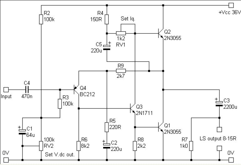
Compare this circuit with the 1970 approved modifications by JLH
Your input set output voltage adjustment network needs to be changed and your Q4 needs supply rail decoupling - the 12k 250uf combination in the attached image.
Attachments
I think in practice you will find the performance of the two arrangements give near identical ripple rejection tbh, the 12k and 250uF being no different to the 100k and 64uF.
ok, I took out the bc212 and, as expected by you, the dc offset jumped to 30V, I also checked the value before r3 and I found 14.5V, after r3 14.4V, so now everything is normal. it remains to be discovered what to do with Q4
incredibly, it worked! I turned the transistor 180 degrees and restored the link that was probably the reverse before. now I can safely get to the midpoint of about 14V.
incredibly, it worked! I turned the transistor 180 degrees and restored the link that was probably the reverse before. now I can safely get to the midpoint of about 14V.
Transistors with BC prefix usually have a lead out from the flat face of CBE with a few exceptions which go ECB. 2N prefix types go EBC.
While BC212 and 2N3906 might be electrical equivalents, as you have now learned, there is a trap if it is assumed the orientation of connections is identical.
incredibly, it worked! I turned the transistor 180 degrees and restored the link that was probably the reverse before. now I can safely get to the midpoint of about 14V.
🙂 well that's good. So it is all OK now I assume... music flowing.
yes, truly awesome music. it's amazing how a simple misconnection can make an entire circuit malfunction. definitely learned not to trust the first datasheet I find, and the transistor itself. now the transistors are more than balanced, instead of heating just one, now they are both ... really cooking temperatures
It's actually amazing it worked at all but in fact transistors can under certain conditions operate with reversed polarity but the gain is very low plus the operating conditions have to fall within a very narrow window for that to happen.
The JLH is a classic design and still up there with the best even today.
The JLH is a classic design and still up there with the best even today.
bias regulation help! 🙂
hi Ian Finch, like Love4Music, I also finished building this schematic, unlike him, I have no problems with regulating V / 2 via RV2, but I have problems with quiescent current, therefore regulating RV1.
Probably I am wrong in directly coupling an amperometer in series to the power supply of the circuit, without any reference resistor, but measuring as I told you, by varying VR1, the amperometer :confuso:measures 1.7 A fixed, without changing anything ... for the bias adjustment no need to short circuit the amplifier input, right? also in the formula you described: I = E / R, what do you mean by E? sorry for the trivial question and thanks for the help!
Let's say that the adjustment you're looking for is "DC offset" rather than bias. The bias adjustment is for the current passing through Q1 and Q2 from collector to emitter but unfortunately, you can't measure it directly because there are no emitter resistors to use for a reference in this this version.
If you also want to measure and adjust bias current, you can calculate that by fitting a small value (say, 0.2 - 0.5 Ohms) 5W resistor in series with the +36VDC power lead. Measure voltage across the resistor then I=E/R and you have the total current drawn by the ampliier, which is only a fraction more than the output stage bias.
hi Ian Finch, like Love4Music, I also finished building this schematic, unlike him, I have no problems with regulating V / 2 via RV2, but I have problems with quiescent current, therefore regulating RV1.
Probably I am wrong in directly coupling an amperometer in series to the power supply of the circuit, without any reference resistor, but measuring as I told you, by varying VR1, the amperometer :confuso:measures 1.7 A fixed, without changing anything ... for the bias adjustment no need to short circuit the amplifier input, right? also in the formula you described: I = E / R, what do you mean by E? sorry for the trivial question and thanks for the help!
- Home
- Amplifiers
- Solid State
- JLH 2000 amplifier