Hi folks
I bought one of those 'JLH 1969 Headphone Amp' PCBs from ebay, which isn't actually a design by JLH himself, it just uses the 1969 design as a basis.
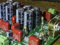
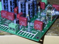
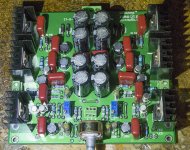
I went to the trouble of sourcing all original components, NOS transistors, Wima and Rubycon caps, Neohm, Welyn and Vishay resistors, no cheap Chinese parts at all (other than the heatsinks).
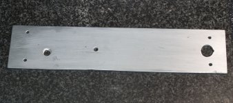
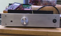
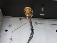
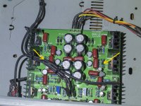
For a chassis I took an old Show PA-18 mono PA amp and stripped it down, then bolted a 3mm piece of aluminium on the front.
Last night I came to fire it up for the first time and when I hit the power switch, the blue led came on, but immediately, smoke was emitted, so I turned it off.
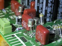
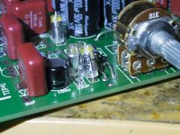
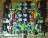
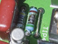
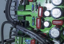
On inspection, two resistors have burned out, it was only powered up for a second or so, so hopefully not much else ha been damaged.
Anyone got any idea where to start diagnosing and repairing this thing? This is my very first ever amp build to reach completion, so I'm a bit clueless where to start.
I bought one of those 'JLH 1969 Headphone Amp' PCBs from ebay, which isn't actually a design by JLH himself, it just uses the 1969 design as a basis.
I went to the trouble of sourcing all original components, NOS transistors, Wima and Rubycon caps, Neohm, Welyn and Vishay resistors, no cheap Chinese parts at all (other than the heatsinks).
For a chassis I took an old Show PA-18 mono PA amp and stripped it down, then bolted a 3mm piece of aluminium on the front.
Last night I came to fire it up for the first time and when I hit the power switch, the blue led came on, but immediately, smoke was emitted, so I turned it off.
On inspection, two resistors have burned out, it was only powered up for a second or so, so hopefully not much else ha been damaged.
Anyone got any idea where to start diagnosing and repairing this thing? This is my very first ever amp build to reach completion, so I'm a bit clueless where to start.
Attachments
-
 P1240017.jpg110.8 KB · Views: 500
 -
 P1270018.jpg116.1 KB · Views: 493
 -
 PC020006.jpg238.3 KB · Views: 533
 -
 PC020009.jpg267.5 KB · Views: 484
 -
 PC020011.jpg216.2 KB · Views: 520
 -
 PC060019.jpg185 KB · Views: 176
 -
 P1270020.jpg120.2 KB · Views: 160
 -
 P1270024.jpg195.9 KB · Views: 180
 -
 PC020010.jpg245.4 KB · Views: 186
 -
 PC020012.jpg202.3 KB · Views: 178
Last edited:
when I hit the power switch, the blue led came on, but immediately, smoke was emitted
Post your schematic and parts list.
Hi Rayma
I don't have a schematic, I'll have to look for one on the interwebs.
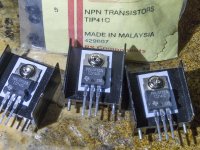
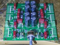
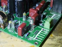
Parts, I just used what was printed on the PCB. The main output transistors are original TI made TIP41C, the other transistors are original TO-18 2N2222A and 2N2907A, the latyter were made by Raytheon, I forget who made the others. Caps are Wima MKC4 0.1uF (the deep red boxes), the electrolytics are Rubycons, 1000uF 50v and 100uF 25v with a few RIFA polystyrene caps in the picofarads range. Resistors are all the correct values as printed on the board, a mix of 0.6w Neohm and Welyn and Vishay 0.25W, with some 1W ones; all are metal film types. I think the ones that have burned are 1W types as they are larger.
I don't have a schematic, I'll have to look for one on the interwebs.
Parts, I just used what was printed on the PCB. The main output transistors are original TI made TIP41C, the other transistors are original TO-18 2N2222A and 2N2907A, the latyter were made by Raytheon, I forget who made the others. Caps are Wima MKC4 0.1uF (the deep red boxes), the electrolytics are Rubycons, 1000uF 50v and 100uF 25v with a few RIFA polystyrene caps in the picofarads range. Resistors are all the correct values as printed on the board, a mix of 0.6w Neohm and Welyn and Vishay 0.25W, with some 1W ones; all are metal film types. I think the ones that have burned are 1W types as they are larger.
Attachments
Here is supposedly the schematic, I found it here:
NEW JLH HOOD1969 Class A Headphone power amplifier DIY Kit Preamplifier kit-in Headphone Amplifier from Consumer Electronics on Aliexpress.com | Alibaba Group
Sadly it's not very clear, I'll try to find a better version.
NEW JLH HOOD1969 Class A Headphone power amplifier DIY Kit Preamplifier kit-in Headphone Amplifier from Consumer Electronics on Aliexpress.com | Alibaba Group
Sadly it's not very clear, I'll try to find a better version.
Attachments
Looks like 5.1 ohm and based on the schematic R4 and R5 connected directly to the + rail
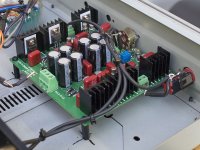
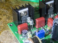
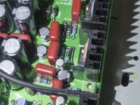
Also, are the heatsinks connected to ground ? If so, are the TIP42 isolated from the small heatsink? I see a thermal pad but the screw going through must not touch the heatsink. The sell kit for mounting TO-220 transistors. Simply check w an ohmmeter to see if any pins of the TIP42 has continuity w the heatsink.
For R4, R5 to blow you probably have a short-circuit somewhere.
You could temporarily replace these 2 resistors by some fuses.
This circuit is known to have a big dc offset drift so a servo circuit is almost mandatory. This can be added later once the unit is working.
BR
Eric
Last edited:
Hi Eric
Thanks for that, I have some fuses and inline holders, I'll get the iron out tomorrow and replace the resistors (it's approaching 1am here so nearly bedtime).
Being my first ever amp build, I expected to have some issues, but I;m a firm believer in the 'learn by making mistakes' approach.
What value do you suggest for the fuses?
Also, are the heatsinks connected to ground ? If so, are the TIP42 isolated from the small heatsink? I see a thermal pad but the screw going through must not touch the heatsink. The sell kit for mounting TO-220 transistors. Simply check w an ohmmeter to see if any pins of the TIP42 has continuity w the heatsink.
Oh balls, I forgot to fit plastic washers so yes, there is a connection between those trannies and the heatsinks. I bet that's the problem....
I'll replace the nuts and bolts with nylon ones and cross my fingers that I haven't friend the trannies.
Many thanks for being so eagle-eyed and spotting that!
I've replaced the metal bolts with nylon ones
Use a meter to verify no contact. Unfortunately the nylon hardware
will deform because of heat at some point.
How exactly do I verify there is no contact? Put one probe of the meter on the heatsink and the other on the metal tab of the tranny?
Shame about the nylon issue, but as long as it gets it working. I'll have built other headamps before too long so if this one ends up dying, no great loss, it is all about learning at this point.
Shame about the nylon issue, but as long as it gets it working. I'll have built other headamps before too long so if this one ends up dying, no great loss, it is all about learning at this point.
How exactly do I verify there is no contact? Put one probe of the meter on the heatsink and the other on the metal tab of the tranny
Exactly, make sure you scratch the paint a little
Well, it turns out the amp is working properly and the fault is with the headphones - tried a different set and the amp is putting out two channels and sounds pretty good I think.
Now, what about this DC servo additional circuitry? Is it a fairly simple upgrade?
Also, what about input/output capacitors?
Now, what about this DC servo additional circuitry? Is it a fairly simple upgrade?
Also, what about input/output capacitors?
Hello Ian,
I knopw it's 2 1/2 years later , but your posting has described exactly what I have just done with my 'JLH' headphone amp kit. I thought I could do without the insulators as it looks to me that there is no connection to the heatsinks in the PCB. I will fit new parts and try again.
I knopw it's 2 1/2 years later , but your posting has described exactly what I have just done with my 'JLH' headphone amp kit. I thought I could do without the insulators as it looks to me that there is no connection to the heatsinks in the PCB. I will fit new parts and try again.
Thanks Ian
Thanks! At least it was so cheap I will take it as educational if it never works properly. I recently bought a PCB from KMTech for the hybrid headphone amp ("NP-100v12: 12AU7 (ECC82) / IRF510 Headphone Amp"). No problems there. It sounds excellent, so I'm not short of DIY headphone fun.
Thanks! At least it was so cheap I will take it as educational if it never works properly. I recently bought a PCB from KMTech for the hybrid headphone amp ("NP-100v12: 12AU7 (ECC82) / IRF510 Headphone Amp"). No problems there. It sounds excellent, so I'm not short of DIY headphone fun.
Educational?! Hah! You'd think that by my age I would have learned that eyes are very good things and should be used occasionally. The upper surface of this board is mostly copper and one pin of each heatsink is soldered to it. So there's why I did need to use the insulating pads and washers.
I've read that a couple of the electrolytic caps are backwards on the silkscreen.
JLH Headphone Amp
The JLH "original" schematic can now be found here:
The Class-A Amplifier Site - JLH Headphone Amplifiers
And there's a discussion about getting correct output bias:
JLH Headphone Amp
"Forgetting the cap changes for now, the general consensus was:
R9/10 change from 2K2 to 3K3
R21/22 change from 1K to 10K (important because its in dc offset circuit)
R19/20 change to less than 220K, around 100K
Replace the 2V7 zener with 3 or 4 1N4148 diodes in series"
JLH Headphone Amp
The JLH "original" schematic can now be found here:
The Class-A Amplifier Site - JLH Headphone Amplifiers
And there's a discussion about getting correct output bias:
JLH Headphone Amp
"Forgetting the cap changes for now, the general consensus was:
R9/10 change from 2K2 to 3K3
R21/22 change from 1K to 10K (important because its in dc offset circuit)
R19/20 change to less than 220K, around 100K
Replace the 2V7 zener with 3 or 4 1N4148 diodes in series"
Last edited:
Reversed electrolytic capacitors
Thanks dangus for the reminder. I had seen this in the large thread you referred to, and I went back to look again. I have fitted larger (and maybe better) caps with the terminals reversed as advised. You may have seen that I made the error of not insulating the transistors from the heatsinks (which it turned out were grounded) and burned up a couple of resistors. I've made good and replaced the resistors each with a pair of 10 Ohm -which is what I had spare. The circuit is making nice music but it was only tested on the table with inputs and outputs made roughly. I need to do proper wiring, and I will make the suggested changes to the earthing as in the long thread from MilesCampbell, and then try the changes that you have referred to.
Thanks dangus for the reminder. I had seen this in the large thread you referred to, and I went back to look again. I have fitted larger (and maybe better) caps with the terminals reversed as advised. You may have seen that I made the error of not insulating the transistors from the heatsinks (which it turned out were grounded) and burned up a couple of resistors. I've made good and replaced the resistors each with a pair of 10 Ohm -which is what I had spare. The circuit is making nice music but it was only tested on the table with inputs and outputs made roughly. I need to do proper wiring, and I will make the suggested changes to the earthing as in the long thread from MilesCampbell, and then try the changes that you have referred to.
- Home
- Amplifiers
- Headphone Systems
- JLH 1969 Headphone Amp