Yes, it is connected to base of Q1 (screenshot don't show the cross point, sorry).
Guan
OK, just make sure that it is connected in your sim schematic. These things tend to propagate themselves undetected.
Jan
 Merry Xmas Mooly

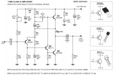
Feedback resistor R7 and R8 is much smaller than that in the original design (2.7k and 220 respectively). Changing to larger R7 and R8 (while keeping their relative value) gives larger THD, but why?
3. R5 and R6 are small resistors in value. Are they thermal stable. How about the Q-point stability?
4. R9 is changed to small 120 (original is 2.2k) to lower the static current passing through MJL3281AG. But is it still thermal stable? I don't know its functionality.
2. Simple- 220 ohms gives a fairly high local feedback, so the overall input stage impedance is about 270 ohms approx, setting the input stage gain to 4mA/V. If you reduce this to approx 50 ohms the net impedance is about 100 and gain 10mA/V, giving 2.5x more OLG and therefore lower distortion.
3.You need to read about the quiescent current in one of the original articles or descriptions. R5 and R6 need to be adjusted to set the quiescent current. Using fixed values means that the current can be variable depending on the gain of the output transistors.
The thermal stability of the resistors is not so much an issue, but ensuring the output stage current is set correctly is.
4. One DIY'er suggests lowering the value of R9 to 1k. While a lower value is preferable in most circuits, it could make the quiescent current stability worse as Vbe's reduce with temperature. The lower the impedance, the more that the base current can increase, which is less stable in this design. I previously suggested keeping it at 2.2k for this reason.
I have not encountered any issues with using high frequency output transistors in practice, as long as a phase lead compensation capacitor is used. That needs to be selected carefully, however, as too high a capacitor can cause problems as much as too little.
These points have been raised in the JLH thread, but are buried in 5,000 plus comments.
...Change almost every R base on THD measurement ... R5 and R6 are small resistors in value. Are they thermal stable. How about the Q-point stability?...
Nevermind stability. SPICE is stupid. YOU should work it out on a matchbook (see attached). Or put an Amp Meter in SPICE and think about what you get.
The load can swing say 13V peak in 8 Ohms, or 1.6 Amps. The idle current for push-pull class A should be half of that, 0.8 Amps. Less, and it won't swing in 8 ohms. More, and your heat increases.
Yes, THD goes down. Gain, and therefore distortion, are functions of the ratio of idle current to signal current. So it "makes sense" to run idle current much higher than signal current.
In _small_ audio, with 1mW signals and 300mW parts, this does work fine.
But this is a POWER amp. At best it will run hot. This dominates size and cost. Anything over a part-Watt you *really* want to keep an eye on heat/power and make wise decisions.
You reduced R5R6. Circuit operation is simple. R5R6 current splits into Q3b and Q4b (and R9). For reasonably matched Q3 Q4, each gets about half. This current, times hFE of Q3 Q4, IS the output stage idle current.
Reducing R5R6 has INcreased output stage idle current. And hFE is not tightly controlled. Matchbook says idle current is 1.05A to 2.1A. Could be 2.5 times what you need! Yes, this may be ~~2.5X less THD. But the extra 40+ Watts of heat is a LOT to spend for a mere 2.5X less THD. It nearly triples the size/weight of power supply and heatsinks.
If anything, R5R6 should be *larger* than in 1969 because 2018 BJTs tend to be higher hFE than in 1969.
As you have also noticed, reducing R8 (and R7 in proportion) raises open-loop gain and thus increases gain of Q1, increasing overall NFB, and lowers THD. Q1 at 0.15mA has ~~200 ohm hIE, so going much lower is diminishing returns (but the amp has the grunt to pull a low-Z NFB network). Letting R8 be 100r allows C4 to be a less-ginormous 100uFd-1,000uFd while still passing all the bass a 10 Watt amp can put to a domestic loudspeaker.
High-level thought: the 1969 is a "classic" not because of low THD but because its simple serendipitous topology makes "simple sweet" distortion which does not annoy the ear. If you hot-rod it, raise gain and NFB, the low-order THD goes down, sure, but the higher harmonics may come UP; moreover the intermodulation distortion (haze on complex passages) is liable to come up. This can be controlled with even more NFB, but there isn't all-that much gain and NFB possible in just four BJTs.
Build it like it was 1969 again, except fiddle R5R6 for idle current just a hair more than the load needs.
Attachments

Oh, thermal stability: as shown, this is current-drive, not Vbe sensitive (slightly due to R9). Assuming R5R6 are thermally stable (close enough for audio), the main parameter is hFE tempco of Q3 Q4. Datasheet shows 40% rise of hFE for 75 deg C rise. Since this is constant heat, Q3Q4 will hot-up before you get the needle in the groove. Select heatsink for less than 50 deg C rise at nominal power (here, 12W/device), select R5R6 for <0.5A dead-cold (look fast) and then for 0.85A when full hot.
Any decent SPICE has a Parameter for temperature. I have often swept this from 25C to 50C to check what happens when it gets hot. This *assumes* the SPICE Model correctly implements the basic semiconductor action-- this is intrinsic to the canonical SPICE equations but a clumsy model maker could foul it up.
Any decent SPICE has a Parameter for temperature. I have often swept this from 25C to 50C to check what happens when it gets hot. This *assumes* the SPICE Model correctly implements the basic semiconductor action-- this is intrinsic to the canonical SPICE equations but a clumsy model maker could foul it up.
Some SPICEs (perhaps most) are not very good at thermal simulation (yet). A general sweep of temperature is fine as a DC check but is not usually representative of the actual circuit where some transistors run quite hot and hotter than the others.
What we need is a SPICE simulator that knows about heatsinks and thermal resistances so can simulate the junction temperature in individual devices. It may be possible in some simulators to set individual device temperatures, or develop specific models as a work-around but this is cumbersome.
What we need is a SPICE simulator that knows about heatsinks and thermal resistances so can simulate the junction temperature in individual devices. It may be possible in some simulators to set individual device temperatures, or develop specific models as a work-around but this is cumbersome.
An interesting reconfiguration.
I have not explored this inverting mode set-up, but I have explored the more conventional non-inverting version of the design with the input to Q4 and usual feedback to Q6 is that? - not quite clear.
What this misses is that the original JLH design was rather subtle in its design. JLH used the non-linearity of the input transistor and driver to compensate somewhat for the increased distortion in the output stage as a result of largish gain variation with current, (peaking at a moderately low current, then falling with higher currents) which the older transistors exhibited. This means that the distortion with a diff input stage actually increased. Surprisingly, perhaps.
However, with modern linear gain transistors the distortion may be similar to the original or possibly slightly better, but that remains to be seen.
If you go to the trouble of using a diff input stage, most people might wonder why you would not omit the output capacitor and use a split rail supply. The inverting input stage, however, creates an imbalance that is slightly harder to offset, but you could do it with a 20k input bias resistor (balancing R9) if it is bypassed with the 100uF cap., but it may contribute an odd LF bounce (at some low frequency).
A 2k input impedance is quite low. You would need a preamp with a particularly low output impedance if it is not going to reduce the gain too much, or add another buffer (see the JLH69 thread).
And, another concern is that you've added a Miller capacitor which JLH did not like, as this introduces slew rate limiting at a lower frequency which may, depending on the input, generate transient distortion (though many suggest typical signals don't cause this in practice). I'm not sure that the effects will be ameliorated by the 11pF phase-lead capacitor as that would be too small an impedance over the same frequency range.
You may well need to make R1 variable to adjust for gain variations in the output transistors.
Unlike the older transistors, the gain of the MJL3281A's increases with temperature and only shows convergence at currents around 6A. There will be some increase in quiescent current as the devices warm up, therefore, and that means adjusting the current once warm - with a delay in being able to reach peak output during the warm-up, though that may not be too much of a concern.
I agree that the 200 ohm base resistor balancing is useful in balancing the currents in the output stage.
Despite all of my initial thoughts, the input stage current runs at 6mA and that would drive the Miller capacitor to quite high frequencies. So it could perform well at audio.
Which means, in summary, I think it is really only the input impedance being low which may be the biggest issue for some.
Last edited:
An early 1960 US Patent (I don't remember the number) had an amplifier circuit as JLH1969 for a telephone line. The signal was fed to the emitter of the input transistor together with the NFB.
That would have a low input impedance then.
But this isn't the first time an inverting configuration has been used for an audio amp.
The Quad 303 is probably the best known hifi example, but even that design needs updating to use modern transistors as the original really isn't state of the art any more. (but could be).
Many early Class AB designs from the 60's and early 70's using just one input stage transistor (now known as VAS) and a driver/output pair and had inverting gains and lowish input resistances in the region of 3k.
But most designs these days generally have 10k input impedance or higher.
There have been occasional designs using the inverting configuration but apart from the old 60's generally have higher input impedance too.
More to the point, you'll find that the cost of the fake Sanken power transistors is probably not much more than the usual TIP2955 or fake 2SJ554 mosfets such as are supplied in the cheapest kits currently available. Fake? Yes, when you see signs of manual sanding of the original markings, you can be certain you have a fake of some type. When the kit price is so low, be prepared to spend much more to get the correct or at least genuine power semis.I am perplexed by the sanken A1216 kit from e-bay. JLH himself explained in one of his books that output transistors should be slow, not fast as Sankens are......
Last edited:
Somewhere in the JLH69 thread I posted results of tian probe simulations of JLH variants.
Here is a summary.
The "slow" sim uses a 2N3055H model (a realistically slow one not a recycled epi model);
the "medium" uses a 2N3715/6 type (epi) device and the fast uses a 2SC5200 model.
The fast+cap uses a 33pF capacitor across the feedback resistor.
The most stable results, by a long way, is the slow. This essentially supports JLH's conclusion. But it only has a 450kHz-ish loop gain frequency response.
The "standard" epi device is stable as far as my results went (stopped at 100MHz, but needs another decade to check)
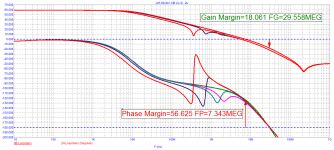
while the "fast" circuit, though (apparently) stable has the lowest margins which are improved with a small feedback capacitor.
Thus, using fast transistors in the circuit without modification may well be more susceptible to parasitic lead inductances and capacitances. But, adding the cap also extends the UGLF so that may also create a problem itself if screening etc is not adequate.
JLH10 UGLF Phase m gain m
Slow 475k 90 >>40dB
Medium 1.5M 76 >60dB
Fast 3M 76 30dB
Fast+cap 15M 100 >30dB
Here is a summary.
The "slow" sim uses a 2N3055H model (a realistically slow one not a recycled epi model);
the "medium" uses a 2N3715/6 type (epi) device and the fast uses a 2SC5200 model.
The fast+cap uses a 33pF capacitor across the feedback resistor.
The most stable results, by a long way, is the slow. This essentially supports JLH's conclusion. But it only has a 450kHz-ish loop gain frequency response.
The "standard" epi device is stable as far as my results went (stopped at 100MHz, but needs another decade to check)
while the "fast" circuit, though (apparently) stable has the lowest margins which are improved with a small feedback capacitor.
Thus, using fast transistors in the circuit without modification may well be more susceptible to parasitic lead inductances and capacitances. But, adding the cap also extends the UGLF so that may also create a problem itself if screening etc is not adequate.
JLH10 UGLF Phase m gain m
Slow 475k 90 >>40dB
Medium 1.5M 76 >60dB
Fast 3M 76 30dB
Fast+cap 15M 100 >30dB
Last edited:
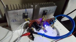
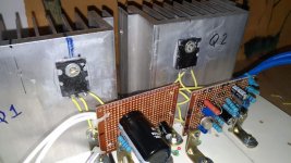
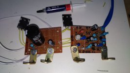
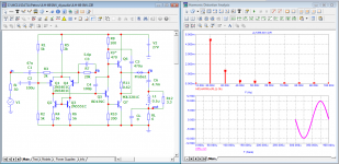
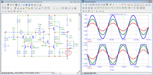
My JLH 1969 (10W) circuit
Hi forum!
I did only one side of the circuit. I'll do the other one to make it stereo.
Circuit power supply: 19VDC
IQ = 1.2A
Hi forum!
I did only one side of the circuit. I'll do the other one to make it stereo.
Circuit power supply: 19VDC
IQ = 1.2A
Attachments

that's what happenedWhat do you think about this one?

Attachments
- Home
- Amplifiers
- Solid State
- JLH 1969 Explanation