I'm not explaining that very well. Its taking a minute because it thinks there is an offset...
With no offset present (board not connected to the amp output) does it have a built in 'speaker delay' time of say 5 seconds.
With no offset present (board not connected to the amp output) does it have a built in 'speaker delay' time of say 5 seconds.
This is what I'm thinking. Look at this image. The amp output is set to 20 volts DC here and appears 1 second in. The output side of the cap is charging via a 100 ohm here and after a few seconds the voltage has fallen to a very low value.
So if your board has a delay you could add a highish value resistor which would charge the cap in a few seconds.

So if your board has a delay you could add a highish value resistor which would charge the cap in a few seconds.
Yes, Mooly, that's exactly what I'm going to do. Unfortunately, it will take some time. So I'm taking a time-out. 🙂 I'll definitely let you know the results.So you are going to try some more of those same MJ's from elsewhere?

This is the board that I have.This is what I'm thinking. Look at this image. The amp output is set to 20 volts DC here and appears 1 second in. The output side of the cap is charging via a 100 ohm here and after a few seconds the voltage has fallen to a very low value.
So if your board has a delay you could add a highish value resistor which would charge the cap in a few seconds.
View attachment 1346568
What you propose is to add a resistor of 100ohm across the L&R in and ground ?
Yes, one resistor for each channel. Try 100 ohm. For permanent use a 1 watt type. A carbon or metal film should be fine as it sees only a short duration current spike and it will always run cold.
@Mooly @NanoFarad
100ohm seems to work.
It will do for now but I think I will buy new relay's and add a 10ohm/10W on the NC.
With the 100ohm it will be paralleled with the speaker load right? If 1A goes through the speaker (10ohm), 0,1A will go through the 100ohm I guess.
100ohm seems to work.
It will do for now but I think I will buy new relay's and add a 10ohm/10W on the NC.
With the 100ohm it will be paralleled with the speaker load right? If 1A goes through the speaker (10ohm), 0,1A will go through the 100ohm I guess.
Try higher if you want. 150 ohm, 220 ohm. The added load will make no practical difference to normal use.100ohm seems to work.
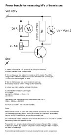
My power setup for measuring hFe of transistors.This is pretty typical behaviour for damaged transitions; they may have arrived damaged, or you may have damaged them when testing. Are there any transistors you have not tested, from the Mouser batch you ordered? If yes, try those.
I carried out the measurements in quite harsh conditions: the common supply voltage was 24 volts, and the current was 2 amperes. But the MJ15001G transistor has a power of 200 watts, and the maximum collector current is 15 amperes. I very carefully monitored the resistance of the variable resistor Rv, so as not to damage the base of the transistor. The transistor and the power resistor were mounted on a fairly large heatsink with an area of 1.2 square meters. After full heating, its temperature did not exceed 56 degrees. The transistors were attached to the heatsink with thermal paste to ensure a good heat transfer coefficient.
Question: could I damage the junctions of the MJ15001G power transistors on such a rig under the above conditions?
Attachments
Last edited by a moderator:
If you opened the transistor fully, i.e. if the Vbe was much more than 0.6V AND the transistor (big resistor) overheated for too long.... then possibly yes. Difficult to say...
I wrote down the data from the voltmeter Vb for all the measured transistors: the voltage on the resistor Rb fluctuated from 0.978 to 1.118 Volts. The average time for testing a transistor was about 5 minutes. The radiator was constantly kept hot and therefore the testing was relatively fast.
Question: could I damage the junctions of the MJ15001G power transistors on such a rig under the above conditions?
Not easily in a set up like this. The method is OK, you are really just calculating base current and collector current and dividing one into the other to get the gain.
You should've used an additional voltmeter to keep Vbe in check, as per my previous post... or, a lab power supply where you'd limit the total current supplied to that test circuit.Question: could I damage the junctions of the MJ15001G power transistors on such a rig under the above conditions?
The problem I see with your gain test is that the transistor is dissipating about 24 Watts, and therefore MUST be well heat sunk. Without a heat sink, even a TO-3 can only handle a couple Watts. In a few seconds the silicon chip will melt without a big heat sink. Helping someone trouble shoot their problems is mostly about guessing what they are not telling you.
If the 100 Ohm bias resistor is a 3-Watt resistor and getting hot then you have at least 1.5 Watts and 12 Volts on it, and the Pot should be getting even hotter. It seems the wiring is not what it should be. Is there any physical difference between transistors that would explain that?
If the 100 Ohm bias resistor is a 3-Watt resistor and getting hot then you have at least 1.5 Watts and 12 Volts on it, and the Pot should be getting even hotter. It seems the wiring is not what it should be. Is there any physical difference between transistors that would explain that?
steveu, you either didn’t read my post or I didn’t understand you. "The transistor and the power resistor were mounted on a fairly large heatsink with an area of 1.2 square meters. After full heating, its temperature did not exceed 56 degrees. The transistors were attached to the heatsink with thermal paste to ensure a good heat transfer coefficient".
The base resistors are mounted separately from the radiator - they are not powerful and do not heat up.
The base resistors are mounted separately from the radiator - they are not powerful and do not heat up.
Got myself couple of dozens AL100 and decided to make JLH with mix of soviet germanium + AL100's 🙂
Now it's time to design a board. I'm trying to fit it into case from Aliexpress.
Got the boards😎
Now need to wait for the main component - the case. Can't do much without heatsinks 🙂
- Home
- Amplifiers
- Solid State
- JLH 10 Watt class A amplifier