I know purists will find it blasphemy ...
It's not so much "blasphemy" as needing to understand the new/different noise sources we have and their characteristics.
Almost as important is how much care and attention went into the implementation - I'd be horrified if a $$$$ lab grade bench supply (using SM tech) didn't perform better than a cheap linear wallwart from the nickle-and-dime store.
But if cost is no object, the theorist in me will go for choke input every time, with shunt regulation as needed.
How you describe the JLH is open to interpretation.
I would call it current feedback because of the low impedances at the point feedback is applied (emitter of the input stage), but the reality is that it fits neither description (VFB or CFB) very well.
I would call it current feedback because of the low impedances at the point feedback is applied (emitter of the input stage), but the reality is that it fits neither description (VFB or CFB) very well.
Member
Joined 2009
Paid Member
The feedback loop senses voltage at the output feeds it back to the inverting input of a single transistor error amplifier at the input. But because this is a low impedance inverting input folk like to call it 'current feedback' - can't argue with the masses but it's kind of silly to name it current feedback when there are amplifiers that actually sample the current at the output to derive their feedback signal.
Voltage feedback as its directly monitoring the voltage across the load - how does one arrive at the "current feedback" option?
Voltage feedback as its directly monitoring the voltage across the load - how does one arrive at the "current feedback" option?
The voltage at the load is what drives current into the 'input terminal', in this case the emitter of the transistor. When that terminal is current fed (and its low impedance dictates that it draws significant current) then we can call it a current feedback type of circuit.
Look at a typical application note for a true CFB opamp. The major difference is the impedance of the circuitry around the input terminals.
The JLH is in between, it has a high-ish impedance on its non inverting input and a low impedance on its inverting input, an impedance that is not high enough to put it in the VFB category and not low enough to be true CFB .
I just tested mine with a 25vdc SMPS and it sounds lovely. No ill affects that I can hear and ran at 2A without a problem. I know purists will find it blasphemy but I was quite pleasantly surprised.
If my JLH 1996 updated version sounds better with the lab smps compared to a 300va unregulated supply, I'll just keep using it.
I'm no purist, so my ears will decide.
I'm using this SMPS and could not ask for better. I don't think anyone could
DIY one for less $$$.
RS-150-24: MEAN WELL: Power Supplies & Wall Adapters
DIY one for less $$$.
RS-150-24: MEAN WELL: Power Supplies & Wall Adapters
If my JLH 1996 updated version sounds better with the lab smps compared to a 300va unregulated supply, I'll just keep using it.
I'm no purist, so my ears will decide.
Could you describe the differences you hear between smps and unregulated?
My own includes one unregulated power supply per channel with 40 1500uf capacitors . I find the result very good, I would be curious to test a smps. I need 32 v, not easy to find...
Hello,
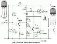
I buyed the 1969 version of the JLH amplifier :
1 pc JLH 1969 classe A bord de l'amplificateur haute qualit PCB assembl MOT / 2N3055 dans Amplificateurs de Appareils lectroniques grand public sur AliExpress.com | Alibaba Group
The exact schematic is this one :
I have a few questions about it :
1) I can lower the gain (with R4 and R5) ? Until what value ? Is the amplifier stable with a unity gain ?
2) I am currently using a 15V DC power supply to power this circuit (the quiescent current is 0.5A). This voltage is enough for my usage (the amplifier feeds a 110dB/watt compression) but I am wondering if raising or lowering the power supply voltage can lower the output distortion.
3) My 15V power supply is rated 2A max. Is it enough for feeding two amplifiers ?
I buyed the 1969 version of the JLH amplifier :
1 pc JLH 1969 classe A bord de l'amplificateur haute qualit PCB assembl MOT / 2N3055 dans Amplificateurs de Appareils lectroniques grand public sur AliExpress.com | Alibaba Group
The exact schematic is this one :
An externally hosted image should be here but it was not working when we last tested it.
I have a few questions about it :
1) I can lower the gain (with R4 and R5) ? Until what value ? Is the amplifier stable with a unity gain ?
2) I am currently using a 15V DC power supply to power this circuit (the quiescent current is 0.5A). This voltage is enough for my usage (the amplifier feeds a 110dB/watt compression) but I am wondering if raising or lowering the power supply voltage can lower the output distortion.
3) My 15V power supply is rated 2A max. Is it enough for feeding two amplifiers ?
Last edited:
This is a class A amp. Quiescent current should be between 1.2-2A. You are likely getting distortion because you are running too low a bias.
Member
Joined 2009
Paid Member
Best way to make unity gain is change Q3 for a PNP type.
go here, post number 6:
http://www.diyaudio.com/forums/solid-state/268846-tgm9-my-version-jlh-69-class-amplifier.html
go here, post number 6:
http://www.diyaudio.com/forums/solid-state/268846-tgm9-my-version-jlh-69-class-amplifier.html
Thank you for your response still4given. You raised a very good point. The output transistors are not correctly biased so they don’t work in their linear part.
I raised the bias to 1A by turning the KT2 potentiometer and I think that the sound quality improved, because I am just starting to like the sound of this amp.
So I think I can answer to my question 3) : if the optimum quescent current is 1.2A, I suppose the max current should will be about 2A for each amp. My power supply must feed two amps, so it must be able to deliver 4A peak and a mean current of 2.4A. Is it right ? My power supply is rated at 2A (constant current I guess). I don't know what is the peak current it can deliver. So, as a conclusion, my 15V-2A PS don't seems to be very well suited for this application... But maybe it could be enough for very low level output (driving 110dB/watt high efficiency compressions).
If I raise the power supply from 15VDC to 27VDC, will the output distortion be lowered too ?
Bigun, thank you for showing me you schematic. It is simple and elegant. Maybe I will give it a try in the future. But for the moment, I prefer to stick with the original schematic and the PCBs I have. If I lower R5 to 0 ohms, the gain becomes unity. But what about the amp distortion and stability ? I don't know.
This is a class A amp. Quiescent current should be between 1.2-2A. You are likely getting distortion because you are running too low a bias.
Hello, help me understand,
Where is the quiescent current measured? Is it total current drawn by the amp or is it just the draw by Q1 and Q2 in the above schematic?
Thanks.
Member
Joined 2009
Paid Member
Strictly, it is the current flowing through Q1 and Q2 but since this is much much larger than the current flowing anywhere else in the amplifier you can measure the total current flow through the amplifier as being close enough.
- Home
- Amplifiers
- Solid State
- JLH 10 Watt class A amplifier