Small warning:
I did something like that too. But with my relatively high rail voltages (about + and minus 20V) the Toshiba's 2n3055 where just outside their SOA. One channel repeatedly died on me.
After changing to the new transistors overything is ok.
MArco
Perhaps they weren't genuine devices. 40 volts and a couple of amps (which is more than the JLH runs at) is well within a 2N3055's abilities as long as it is cooled sufficiently.
Small warning:
..... (about + and minus 20V) the Toshiba's 2n3055 where just outside their SOA. One channel repeatedly died on me.
After changing to the new transistors overything is ok.
MArco
I also first started with Toshiba 2n3055 bought from the "_bay" for prototype thinking they were fake. I paid $1/piece. But to my surprise, they did not sound bad at all. I ran them at +/- 25v for quite a while before changing them to MJ15003. The upgrade was a direct swap and no adjustment was needed.
Jaap, if you're concerned by the discussions around the siliconray pcbs that I've started, it's just that it's my first diy amp, so I managed to fry it when I first powered it, and then after powering it second time.. and then after short circuiting some transistor with the test probe.. 😀. no reasons to panic. I'll receive the replacement transistors tomorrow (or so I hope), and come back with the results, of more questions..
Is something wrong with the siliconray PCB's ?
There is a discussion on their board. Error was mentioned but seems like was fixed in later version of the board:-
http://www.diyaudio.com/forums/sili...200659-free-pcb-jlh-2005-class-amplifier.html
I don't use their board so I cannot verify this.
Good news! TCAAS is now back on-line. It is being hosted by ESP (many thanks Rod) and can be accessed using the following link:
The Class-A Amplifier Site
or via the ESP index page (it's in the 'Articles & Information' section):
Elliott Sound Products - The Audio Pages (Main Index)
The Class-A Amplifier Site
or via the ESP index page (it's in the 'Articles & Information' section):
Elliott Sound Products - The Audio Pages (Main Index)
an aside. I used Bourns TIP3055 in Rod Elliots P3 amp with +/- 42V rails with no issue. At least none I was aware of. They worked much better than the SMI types i trialled breifly, but even those didnt fail.
Good news indeed, and good to see your name here again Geoff! Time to dust off my JLH and put it back in service.Good news! TCAAS is now back on-line.
hi,
I finally got my boards working with 2n3055, so thanks to all that helped with advises 🙂
Now I got a few more questions, that I can't figure out:
I got some radiators that I bought for the TO3 case style, but they aren't very big, and the transistors get really hot, like 130 Celsius. Is that to be expected? And should I get bigger radiators, or could there be a problem with the circuit? - it sounds ok, as ok it can considering my source is a PC.
Second, I left VR2 at maximum resistance, If I start to decrease it's value, do I risk to get the Q1 and Q1 hotter? The specs say it can withstand 200 deg Celsius, but I really don't want to risk it.
tanks.
Great to hear you have it working.
Anything over around 50 C in use is too hot for long term reliabilty. The 200 C will be the temperature the silicon can stand with no current or voltage applied. For the transistor to run at its max electrical loading and within its safe operating area then you are looking at keeping it around 25 C.
It sounds like your heatsinks are far to small. The heat problem, as your are finding out is the big big drawback to class A operation.
hi,
... and the transistors get really hot, like 130 Celsius. Is that to be expected? And should I get bigger radiators, or could there be a problem with the circuit? .....
Too hot. As I said in my previous post, I use a silent fan for added cooling. Post a pic of your heat sink so that we can tell if it is under-rated. Class-A amps usually have massive heat sinks. I have my Iq set at 1.2A, which is not as high as some of the others set to. But I still have to add a fan. My amp draws 150W from the mains.
Hi, now I am starting to get a picture of how under rated my sinks are..
here is what I got 🙁 :
http://michaelcarden.net/luxeon/heatsink.jpg
I'll try to put them under a PC CPU fan, to see if I can get any improvements, but I guess I should start looking for something bigger. I was looking into CPU heat sinks, but it seems too complicated to drill them.
AC439, any chance of a picture of your heat sinks?
Hi, now I am starting to get a picture of how under rated my sinks are..
here is what I got 🙁 :
http://michaelcarden.net/luxeon/heatsink.jpg
I'll try to put them under a PC CPU fan, to see if I can get any improvements, but I guess I should start looking for something bigger. I was looking into CPU heat sinks, but it seems too complicated to drill them.
AC439, any chance of a picture of your heat sinks?
Oh no ! Your heat sinks are way too small !!! See my thread below with pics:-
http://www.diyaudio.com/forums/solid-state/207482-my-jlh-1996-evo-output-transistors-questions.html
Thanks!
You saved me the trouble of hacking another project of mine in order to get the fans.
That means back to component hunting!
You saved me the trouble of hacking another project of mine in order to get the fans.
That means back to component hunting!
Yeah, you need much better heat sinks. Also, CPU fans are smaller, spin faster and make more noise. They are not good candidates for active cooling in amps (which we want no distracted noise from anything).
As you can see, my heat sinks are bigger but still needs a fan. I will be building another JLH amp in the future and the first thing I did was to get bigger heat sinks. I have collected four beautiful gold color heat sinks the size of 8.5" x 4" x 3". Each of them can install 4x TO-3 transistors.
As you can see, my heat sinks are bigger but still needs a fan. I will be building another JLH amp in the future and the first thing I did was to get bigger heat sinks. I have collected four beautiful gold color heat sinks the size of 8.5" x 4" x 3". Each of them can install 4x TO-3 transistors.
Still too small
Still too small. You're pushing out c. 50W of heat, you want to keep your heatsinks below 55C
If ambient is c. 30C then you need below 0.5 degrees/watt
Find something like this
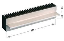 W=300mm, H=75mm, R=0.36d/w
(From Conrad Heatsink MF30-1F-75)
I was looking into CPU heat sinks, but it seems too complicated to drill them.
Still too small. You're pushing out c. 50W of heat, you want to keep your heatsinks below 55C
If ambient is c. 30C then you need below 0.5 degrees/watt
Find something like this
(From Conrad Heatsink MF30-1F-75)
Last edited:
it's worse than that.Still too small. You're pushing out c. 50W of heat, you want to keep your heatsinks below 55C
If ambient is c. 30C then you need below 0.5 degrees/watt
Find something like thisW=300mm, H=75mm, R=0.36d/w
(From Conrad Heatsink MF30-1F-75)
50W into a 0.5C/W sink gives a predicted 25Cdegrees deltaT.
Look up the sink manufacturer's data for deltaT de-rating and you may find that the DF ~1.2 to 1.3.
Apply this to the 25Cdegrees to get a closer prediction for deltaT of ~30C to 33C
Now add this to Ta of 30degC to get Ts ~ 60degC to 63degC.
Then add deltaT for the Rthc-s. Tc = ?
If you look at my sx-Amp here Ovation sx-Amplifier you can get some idea of the heating requirements for a class A amp - in this case 15W per channel. My heatsinks are 0.4W per channel and run at between 60 and 65 C. The quiescent current is 1.4A on 22V rails.
I have finally finished my amp using the Silicon Ray boards. I have undistorted sound on both channels, but I cannot get the dc offset lower thad around 7v (yes v - not mv) on either board. VR1 and VR2 don't seem to have any adjustment left in them (fully clockwise). Should I fiddle with VR3 (current) and then adjust VR1 & 2? It seems to me that if I turn VR1 and 2 anti-clockwise the DC offset just goes up (it started at around 15v) Oddly enough there is no turn on or off thump and no cone excursion.
- Home
- Amplifiers
- Solid State
- JLH 10 Watt class A amplifier