Look, just a question "out of left field" re: temperature of heat sinks. Is there a cheapish way of taking an infra-red photograph (or other method) of a heat sink. RS and others stock packets of temperature sensitive paper strips that can be stuck to a surface and indicate a value but I was just curious if there is a more elegant version that gives a "picture" of what is going on. My current JLH is adequately "sinked" but I am contemplating fabricating half a dozen h/sinks for further versions and want a way of effectively checking them......other than the classic: "if it burns you then its not big enough" method.
Any thoughts. Cheers Jonathan
mobile phone app perhaps? I know that many ccd cameras sense IR but no idea how sensitive they are. U could try using a heatsource in a dark room with your mobile phone. I know my mobiln can 'see' my TV remote IR LED... USB thermocouple dataloggers are a good idea. Theyre cheap and pretty good. I use them occasionally at work, and considering getting one for my reptile vivarium. Heat stickers are a good option, but they are consumables.
I have some silicon ray jlh 2005 boards that now don't have matching transistors (used them on my 69 jlh). I would like to use a TO-247 transistor so I can reuse an enclosure I was using for an F5. Are there any new transistors that are worth playing with? Is there any problem with dropping these guys in there?
http://www.st.com/internet/com/TECHNICAL_RESOURCES/TECHNICAL_LITERATURE/DATASHEET/CD00002853.pdf
What about the new semisouth JFETS, would they need more then just a few resistors changed?
http://www.st.com/internet/com/TECHNICAL_RESOURCES/TECHNICAL_LITERATURE/DATASHEET/CD00002853.pdf
What about the new semisouth JFETS, would they need more then just a few resistors changed?
Try MJL3281A in my unit it works very well. Switching transistors are not ideal for linear applications.
Hi Nico, have you had the opportunity to compare the MJL3281A with MJ15003? I have the MJ15003's in my JLH because the PCB was made to fit these but would like to change them if it is worth it. The system I have sounds great on the whole but vocals are not as good as I would like. Don't know if it will help, any advice?
Hi Nico, have you had the opportunity to compare the MJL3281A with MJ15003? I have the MJ15003's in my JLH because the PCB was made to fit these but would like to change them if it is worth it. The system I have sounds great on the whole but vocals are not as good as I would like. Don't know if it will help, any advice?
Yes I have had both in the same vintage design. Both from On-Semi. If I say I can hear a difference, then I would be dishonest and misleading you. The MJL3281 is a lot easier to mount, but that is about it. Both are very rugged transistors.
If I say I can hear a difference, then I would be dishonest and misleading you..
I don't have specific experience but I just think that the JLH is very sensitive to part change such that it should be easy to recognize change in sound performance.
I have heard people mentioning that one transistor is better than the other transistor even if this other transistor has better specifications. What I can see is that the JLH circuit is very sensitive to part change. When you change the output transistor, the operating points will be changed drastically. So may be if anyone want to change the output transistor with better part, the surroundings operating points must also be adjusted.
I think that this circuit has such characteristics that if you change the output transistor with better (faster) one, the top transistor will be driven harder than the bottom transistor. This is the first thing that I will want to adjust, i.e. to make sure that the bottom transistor be driven slightly harder than the top transistor.
I don't have specific experience but I just think that the JLH is very sensitive to part change....
I don't have specific experience either but I think blond girls are more responsive than brunettes.... But I have heard people mention that red hair girls have better specifications. What I can see is that girls are definitely different from guys....
Last edited:
I don't have specific experience either but I think blond girls are more responsive than brunettes.... But I have heard people mention that red hair girls have better specifications. What I can see is that girls are definitely different from guys....
Hehe I don't understand your analogy. But I was just expressing opinion:
1. I have built many JLH variations, but with older transistors. And I don't even know the specs for the MJL. From my experience with transistors that I used, direct swap of the output stage causes audible difference in sound. Output current can jump dramatically with certain transistor (without bias adjustment)
2. Many mentioned that the MJ15003 is the best (at least with the 2000 version). Many knowledgeable people in the class-A site, so I don't want to question their observation (I believe they have made the necessary adjustments). I myself prefer the better part than MJ15003 in the 96 version.
3. Better parts can make the top transistor be driven harder than the bottom part. This is not good according to JLH himself.
How about darlington as output stages for JLH
Hello Michael. Have you been able to use the MJ11016 to substute output devices in the JLH Class-A. I too did some simulation that shows the darlington output stages has a higher open look gain and lower distortion.Hello, I am a new member to this forum.
Michael
You cannot swap directly. Search for something like "doomsday". There is JLH darlington design in this site.
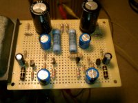
I'm almost finished with a JLH 1969 type amp and am having some issues. First, is this the right place for this or should I start a new thread? Moderators please move if necessary. Ok, in the picture below you will see one side with a 100pF cap between emitter of 3906 and collector of 4401, a suggestion for taming HF. I thought I would see which I liked better. Also, I really wanted the two sides to be symmetrical but I put the right side 3906 in upside down so I had to improvise a little. Here are the problems I'm having.
1. No audio input. When I move to the lead to the other side of the .1uF input cap I get sound but it's distorted. I checked it and it reads good on the meter,
2. The 1/2 +V is about 7vdc instead of ~13vdc. I'm guessing this is the cause of the distortion. Wrong bias?
I've checked voltages against a basic LTSpice sim that I did and things are pretty close except for the 1/2 +V and also between the 560R and the base of 2N3055. I'm only getting about 7vdc instead of the ~13vdc that the sim says.
Right now I'm using 2N3055's but will probably swap out for something better when the bugs are worked out. I'm also using clip leads between the board and output transistors. I'm using a regulated power supply and I'm reading 25.67vdc +V. I'm not sure what I should check next.
Tom
Attachments
hello!
JLH 1969 mosfet class a is easy DIY!
Hi
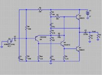
Do you mind posting the schematic ?
thanks
kp93300
I'm almost finished with a JLH 1969 type amp and am having some issues........
Hi Tom,
It would help if you post the exact circuit you are working to so we know what the component references are 🙂
If the mid point volts is incorrect that suggests a front end bias issue.
Here is the schematic that I'm working from. Nico, there are differences between the two sides. The left side was the first side I did. When I did the second side I thought it would be cool to mirror it. Unfortunately, I put the 2N3906 in the wrong way so the emitter was down and not up. I had to fudge around to make it work. Also, there is a 100pF cap on the right side. I think that was a suggestion by JLH to tame HF response. I was going to try it both ways to see.
Tom
Tom
Attachments
Last edited:
Look at your schematic.
R5/6+9 force the input Q4 base to just less than half rail volts. ~12.1Vdc instead of 13.5Vdc.
If your output is considerably less than half volts then you should be able to measure a "voltage anomaly" across R3, and/or Vbe of Q4.
R5/6+9 force the input Q4 base to just less than half rail volts. ~12.1Vdc instead of 13.5Vdc.
If your output is considerably less than half volts then you should be able to measure a "voltage anomaly" across R3, and/or Vbe of Q4.
Last edited:
JLH's measures for more stability involved several components and he clearly stated that all of them were needed for it to work properly - not perhaps your immediate problem but worth considering.
Here's the original schematic that I started from. Mikelm, your right. Here's the quote,
"(It should be noted that either all of these components
should be added or none at all, they are not alternatives.)" I guess I read it wrong. AndrewT when I simulated the circuit, I changed R5 to 113K. That seemed to give me 13.5vdc or 1/2 +V. I used a carbon comp resistor that measured 113K, even though it was a 100k. I thought that would work. I will measure across R3.
Tom
Attachments

- Home
- Amplifiers
- Solid State
- JLH 10 Watt class A amplifier