Good morning,
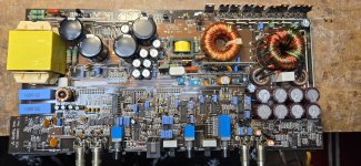
This amp probably has multiple issues. I found a broken RCA pin flopping around inside the case...
First problem! Amp turns on, as soon as power supply is turned on, no remote required. Remote DOES seem to at least turn the power LED on. But that's about it. PS starts switching without remote.
I read on another post, the tech found that the LM324 (U400 on this amp) had no V+ on pin 4. Neither do I. He said he jumped a trace. I can't find any connection to anywhere I've probed that makes a connection to pin 4. What feeds pin 4 it's 12v?
As always, thanks in advance!
Attachments
Good morning Perry,
Tried both settings on the sense switch, no change. It's currently set to off.
With the preamp board removed, R627 (4.7 ohm) has 12.56v on both sides and the power supply is not switching.
With the preamp board in circuit, R627 has 12.50v and other end 11.93v. The power supply is switching.
Tried both settings on the sense switch, no change. It's currently set to off.
With the preamp board removed, R627 (4.7 ohm) has 12.56v on both sides and the power supply is not switching.
With the preamp board in circuit, R627 has 12.50v and other end 11.93v. The power supply is switching.
Ok, not sure why, but I do indeed have the 11.9v on pin 4 now. I have 6.69v on pin 9.
Amp turns on by itself without remote power. Making 81.5v of rail.
Amp turns on by itself without remote power. Making 81.5v of rail.
Did you look for corrosion on the bottom of the board over the power/ground connectors? as is shown in the tutorial? You should use a lighted magnifying glass.
There may have been an intermittent on the preamp board headers. There could also be an intermittent/broken connection on one of the header solder connections.
There may have been an intermittent on the preamp board headers. There could also be an intermittent/broken connection on one of the header solder connections.
Was the first thing I noticed and cleaned up.
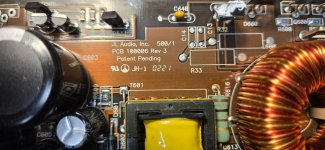
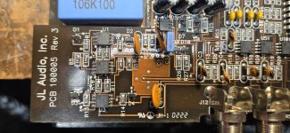
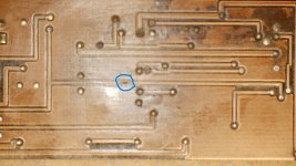
There was definitely corrosion in that area. I used De-Oxit D100L to clean the board. That said, I did also clean the remote terminal and screw because it had corrosion as well. I'll go around and reflow the solder at all the connections in that area. I did notice this area. But when checking from the 2 blue dots, there is continuity.
The connections to J4 header, do seem loose. I have a bunch of jumpers. I'll try to jump them all and see if that makes a difference.
Thanks
Attachments
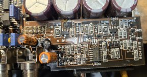
I'd be suspicious of the pads/vias that look rusty. I'd desolder and run a wire through them just to be certain the via couldn't be a problem.

You called that one Perry! Turned out that the via to trace for pin 4 of the 324 was damaged. I couldn't find a wire small enough to fit in the via to make a reliable connection so just jumped pin 4 to the resistor the trace went to. It now only powers up with remote power applied. Thank you!
I'm going to read up a bit more on the 500.1 page and make sure all waves are good. They seem to be. But this is my first one. Then I'll get the outputs in. See how it goes!
Thanks again. 🙂
I'm going to read up a bit more on the 500.1 page and make sure all waves are good. They seem to be. But this is my first one. Then I'll get the outputs in. See how it goes!
Thanks again. 🙂
I have some stranded 14g wire that I use a single strand out of on those repairs. Your board doesn't generally have a problem but on the ones with corroded vias, I drill the solder mask and corrosion from the vias with a #80 drill bit.
If you ctrl-f physically from the start page, you will see the Repairing Physically Damaged Traces page in the directory. Item #6 on that page covers these repairs (on the rev 10 boards, slightly different).
The last updates to the 500 page were on 1/29. If you have an older version, email me.
If you ctrl-f physically from the start page, you will see the Repairing Physically Damaged Traces page in the directory. Item #6 on that page covers these repairs (on the rev 10 boards, slightly different).
The last updates to the 500 page were on 1/29. If you have an older version, email me.
- Home
- General Interest
- Car Audio
- JL Slash 500.1 issues