Yes on Q604 through Q607.
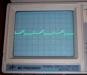
No on Q600 through Q603. Pic of scope on 5V, 5uS, probe at x1 probe placed on gate of Q600.
I back tracked to Q608 & Q609 and they do not have a clean square wave on the emitter but do on the bases. I did not replace the FET drivers, but appears like I need to.
No on Q600 through Q603. Pic of scope on 5V, 5uS, probe at x1 probe placed on gate of Q600.
I back tracked to Q608 & Q609 and they do not have a clean square wave on the emitter but do on the bases. I did not replace the FET drivers, but appears like I need to.
Attachments
Last edited:
Alright replaced both drivers for that bank of FETs, I have nice square wave all the way from the base of the FET drivers to the rectifier pads AND it draws ~1.25A which I think is good.
Of the handful or so of things that generally make amplifiers draw excessive current all seem to check out, at least to the extent that I am capable (no Inductance meter). The +/- 15V power supply is working correctly.
Do you have any more suggestions on what I need to find?
Of the handful or so of things that generally make amplifiers draw excessive current all seem to check out, at least to the extent that I am capable (no Inductance meter). The +/- 15V power supply is working correctly.
Do you have any more suggestions on what I need to find?
Reinstalled the rectifier and powered it up. Current draw was ~1.75A at full on (this is good), however I had not reinstalled Q506 & Q507 from the previous testing a few posts back.
Now, having reinstalled them the full on current draw is up to 7.70A. While I let it sit there and idle, only Q506 & Q507 are getting warm.
I measure ~39VDC from both output terminals to ground, I measure ~10mVDC between the output terminals. Neither of the output inductors warmed up, but I do have clean audio.
So here I figure that somehow either I have damaged Q506/7 with heat reinstalling them (I doubt it), or they were damaged some other way, even though I tested them out of circuit. And yes they were new.
Unless you have other ideas, I'll pull them back out and replace them with another pair.
Unless you find leakage from leg 1 to the other legs (out of the board), they're likely OK but if you are unsure, replace them if you have more on hand.
If that doesn't help, I think you need to go back to having one pair installed at a time to see if one pair causes more current draw than the other.
Did you solder a jumper across the op-amp? If so, did you remove it before reinstalling the outputs?
If that doesn't help, I think you need to go back to having one pair installed at a time to see if one pair causes more current draw than the other.
Did you solder a jumper across the op-amp? If so, did you remove it before reinstalling the outputs?
When I measured them last night, I saw no leakage from leg one to either of the others. I have more, so not a big deal.
The current draw of ~1.75A was with the other pair installed (Q504/5). It climbed to the ~7A after installing the other pair (Q506/7), which get warm at idle. So I think that is the definite problem side.
I did remove that jumper on the op amp a while ago, yes prior to installing any of the outputs.
I forgot to mention, (maybe you implied it) the amp is not cycling on and off anymore.
Now, I can let it sit and idle for several minutes and see if both output inductors get slightly warm before I remove that pair. If one does not, that could be an issue.
I'm assuming that you have a clean rail-rail square wave on the outputs. What is the frequency of that square wave?
I'm not sure you answered this... Did you again (after repairing the power supply), install one pair of outputs (each pair, one at a time) to see if one pair cause more current draw than the other?
You'd probably need to jump the op-amp to cause it to produce a drive waveform.
I'm not sure you answered this... Did you again (after repairing the power supply), install one pair of outputs (each pair, one at a time) to see if one pair cause more current draw than the other?
You'd probably need to jump the op-amp to cause it to produce a drive waveform.
Back on post #34 I reinstalled Q504 and Q505 and have not removed them since, so the power supply was repaired while those were installed. Up until just tonight, Q506 and Q507 have not been in the circuit since post #34. The rectifier was installed tonight. Next, I powered up the amp and read ~1.75A draw. Then I installed Q506/7 and then I read ~7.7A draw after installing Q506/7. Does that answer your question?
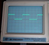
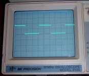
I don't have the same square wave on the outside pads of the rectifier that I did last night, but the rectifier is installed now and was not last night. I'll post a pic of it here in a minute.
I don't have the same square wave on the outside pads of the rectifier that I did last night, but the rectifier is installed now and was not last night. I'll post a pic of it here in a minute.
Last edited:
No, this is the set that was only drawing 1.75A earlier.
However, I didn't have the meter in line last night for this exact test, but the panel meter on the power supply was under 2A so I think we're good here. The heat sink was not getting warm in the output area either.
With all four outputs installed, the heatsink was getting too warm (only around the outputs) in my opinion for idling. The heatsink around the Z44's was still cool.
Later on today, I will put the meter in line to measure the current draw, and then switch to the other pair of outputs and repost what I find there.
I put the meter in line and measured 1.580A current draw at idle. This is with Q504/5 installed, outputs shorted.
Re-checked Q506/7 while out again. Found one of them leaking from pin 1 to pin 3 and tossed it. Re-installed Q506/7, checked total current draw with all four outputs again. It is now down to ~4.08A at idle.
Removed Q504/5 and shorted the outputs. Idle current draw here is 1.025A. I have -15VDC on Pin 2 of Q506 and -15VDC on Pin 3 of Q507, no square wave at all.
- Status
- This old topic is closed. If you want to reopen this topic, contact a moderator using the "Report Post" button.
- Home
- General Interest
- Car Audio
- JL Audio 500/1 v1 Rev. 10 Boards #2