LM555 at U4 on the daughter board? No signal on pin 6. Rises from 1vDC to 2.4vDC after a few seconds - solid DC. Everything is in reference to B- ground/black. Tagging remote briefly.
If you mean the 6-pin IC marked 2G5 at Q512, Pin 6 has the same signal as post #19, LM319 pin 5.
Im not sure if that is right. Whats the board designation for another 555?
Im not sure if that is right. Whats the board designation for another 555?
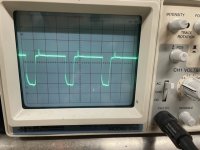
If that's the LM319 near the 555 with the triangle waveform, I'd expect it to be square, top and bottom.
Do you have the pin 1-2 jumper on the 2068 op-amp next to the lm319?
If not, jump it and re-check the pin 12 signal.
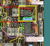
for the 74hc132 that's flanked by the two resistors marked 2201, what signal do you have on pins 3 and 8?
Do you have the pin 1-2 jumper on the 2068 op-amp next to the lm319?
If not, jump it and re-check the pin 12 signal.
for the 74hc132 that's flanked by the two resistors marked 2201, what signal do you have on pins 3 and 8?
I don't have waveforms on those points but I'd expect them to be almost perfectly square.
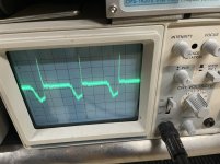
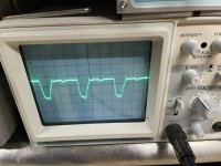
You need to switch to DC coupling. The switching of the gates depends on the voltage applied referenced to ground. I should have noticed this when you first started posting. It's virtually never necessary to take your scope off of DC coupling, especially if you have it set up for differential measurements.
You need to switch to DC coupling. The switching of the gates depends on the voltage applied referenced to ground. I should have noticed this when you first started posting. It's virtually never necessary to take your scope off of DC coupling, especially if you have it set up for differential measurements.
Then there may be a problem with reference voltage to ground in the circuit. I've taken all measurements referencing amp B-.
When I set the scope to DC coupling (99% of the time I keep it there for all repairs) the line jumps outside visible range. If I set the V/Div higher it comes back but then the waveform is too small to see and the trace is showing significant positive voltage.
Theres 4vDC on pins 3 & 8 of the 74hc132 next to the 2201 resistors. Is there a grounding problem going on here? Where is secondary ground for the regulated supply?
Last edited:
There is no secondary ground.
I don't know what your scope is reading because I don't know if your probe is set to 1x or 10x.
What voltage do you read on the ground pin (7) of the 132s?
What's the voltage across pins 7 and 14?
I don't know what your scope is reading because I don't know if your probe is set to 1x or 10x.
What voltage do you read on the ground pin (7) of the 132s?
What's the voltage across pins 7 and 14?
Scope probe has been at 1x. Sorry about the AC vs DC coupling
Actually I think 132s are grounded properly.
132s ground (7) have 0ohms to B-. 0vDC on them.
Across pin 7 & 14 I'm reading 4vDC.
Actually I think 132s are grounded properly.
132s ground (7) have 0ohms to B-. 0vDC on them.
Across pin 7 & 14 I'm reading 4vDC.
Last edited:
What's the output voltage on the 5v regulator in the middle of the board? You can measure from the bottom of the main board.
Are any of the ICs in that area getting hot?
Check the various 10 ohm resistors in that area. Are all within tolerance?
Check the various 10 ohm resistors in that area. Are all within tolerance?
Used heat camera and nothing is getting hot, except Q511 near outputs during rail voltage is getting over 200F. It seems to be operating OK though.
Theres only about ~20 or so 10 ohm resistors in the entire amp. All are measuring OK.
74VHC132. On the one next to 2201 resistors, Should pins 9-14 all be within 20 ohms of each other? The other 132 is not measuring like this. Seems odd or wrong to me.
One of the 74VHC112 is also measuring close to shorted on many pins with pin 16.
Why are you losing a full volt between the 5v regulator and the 132? As far as I know, there is only a 10 ohm resistor between them.
I don't know why you're reading the low resistance between the 112 pins. If you want to know if it's the circuit or the IC, remove the IC and compare the readings on the IC out of the circuit and on the board (without the IC).
I don't know why you're reading the low resistance between the 112 pins. If you want to know if it's the circuit or the IC, remove the IC and compare the readings on the IC out of the circuit and on the board (without the IC).
The 10 ohm resistor between 5v reg and the 132s is ok.
I pulled both 74VHC132 and both are measuring pretty close to shorted across pins 9 thru 14 off the pcb. I also pulled both 74VHC112 and I think those are actually OK.
With 132s removed, powered the regulated side up and I now have good 4.9vDC on pad 14, and also pin 12 of the LM319 is pushing out a perfect square wave.
Time to order 132s, IRF3710Z, and a few other things. Thank you
My gate resistors say 470 on them. No 47This amp came in with IRFZ44 PS fets and 47ohm gate resistors blown in the PS.
On the output side; Q506/Q507 IRF540 completely shorted and the 100ohm resistor very close to the MIC 4427 crispy but still reading well.
I replaced that 100ohm resistor, all 4x IRF540 with IRF540N, and put a single IRF3205 into each PS bank.
Amp powers and plays out of the sync briefly under 4-ohm load to about 10 amps draw.
Seems like it might be OK but I dont really know these amps well enough to verify full operation just yet.
On the 540 vs 540N, seems parts for 540 and 540A may be scarce which is why I installed 540N for right now. The only 540 I am reluctant to try are the expensive Vishay brand.
Any pointers on what else I might need to check next? If the IRF540N are not suitable are there any suggestions? I read the entire JL 500/1 page but there seems to be a LOT going on with these which I am now trying to get familiar with. I usually pass on servicing JL but alas here one is.
Thank you
- Home
- General Interest
- Car Audio
- JL Audio 500/1 rev 10