I generally set my iron to 850F. The solder work goes very quickly and there is not damage on all but the poorest quality boards. 650 may work but not where there is heavy copper.
It could also be that the soldering iron tip isn't tinned properly.
It could also be that the soldering iron tip isn't tinned properly.
I turned up the iron to 800 degrees and soldering became possible.
After replacing all the gate resistors and Q900 and Q901 the voltage is as follows:
Q901: 5.10V
Q902: 5.12V
Next step is to replace the LED's that appear burned out.
Since drive voltages are closer, can the FET's be installed? Or is there something else that needs to be checked before that?
After replacing all the gate resistors and Q900 and Q901 the voltage is as follows:
Q901: 5.10V
Q902: 5.12V
Next step is to replace the LED's that appear burned out.
Since drive voltages are closer, can the FET's be installed? Or is there something else that needs to be checked before that?
The 900 series FETs are for the sub channel. The driver board with the burned LEDs and the working supply are for the front channels. Get those two channels working first.
I replaced the two LED's and powered up the amp. All lights on all cards are now on. I checked the voltages again at Q901 (5.28 V) and Q902 (5.32 V). I will pick up some acetone and thermal compound tomorrow as I understand the transistors and sink need to be cleaned and new grease added.
Is now the time to install the FET's?
Is now the time to install the FET's?
There are no shorts between the legs of any other QXXX transistors. Which bank are they specifically? I can remove them tomorrow and measure them properly.
Never mind, I see you already told me which ones were the sub output channels.
The 900 series FETs are the power supply transistors for the sub channel. Q405, 406, 422 and 408 are the output transistors for the sub channel.
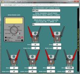
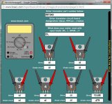
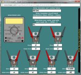
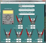
That test procedure is for bipolar transistors but the FETs look OK.
The insulator is mica, not plastic. You can reuse them. They are very fragile so be careful when cleaning them.
The insulator is mica, not plastic. You can reuse them. They are very fragile so be careful when cleaning them.
I cleaned off the heat sink and all the components that make contact with it. Cleaned the mica and applied Wakefield 120-A thermal grease. Re-assembled everything.
When I applied power, all the lights came on on the four cards. Then the low ohm light came on and the power light went off. I had a 5 amp fuse on the supply, don't have anything larger handy, but it blew.
Why would it pull more than 5 amps when idling? Could I have a short somewhere?
When I applied power, all the lights came on on the four cards. Then the low ohm light came on and the power light went off. I had a 5 amp fuse on the supply, don't have anything larger handy, but it blew.
Why would it pull more than 5 amps when idling? Could I have a short somewhere?
Initial current draw will be greater because the caps have to charge. Try it with a 10 amp fuse (when you get them).
I checked the gate resistors that I replaced and all ohm out at 47 ohms. I resoldered the joints and tried again but the fuse blew.
Am I checking the right resistors? I checked the ones on gate legs to the Q900's.
One thing I noted is that my power supply is rated at 8 amps continuous, 15 amps max.
Am I checking the right resistors? I checked the ones on gate legs to the Q900's.
One thing I noted is that my power supply is rated at 8 amps continuous, 15 amps max.
Last edited:
- Status
- Not open for further replies.
- Home
- General Interest
- Car Audio
- JL 500/5 Sub Channel low and distorted


