I have a JL 500/1v2 that keeps burning through resistors and sometimes transistors by the resistors. I am replacing everything with these parts everytime they burn. Sometimes they burn immediately sometimes the next day sometimes after a couple of days. And everytime the amplifier gets extremely hot when this occurs. I don’t use bass boost at all and have tested the amplifier with a picoscope at a 50hz tone to ensure a smooth waveform is produced.
270-47-RC
863-MUR1620CTG
942-IRF3205PBF
942-IRF3710ZPBF
270-47-RC
863-MUR1620CTG
942-IRF3205PBF
942-IRF3710ZPBF
Remove the rectifier and power up the amp. How much current does the amp draw?
Do the PS FETs overheat?
Were the original audio FETs the 3710 or sere they IRF540s?
The 1620 may not be a good substitute if it was not the original part number.
Do the PS FETs overheat?
Were the original audio FETs the 3710 or sere they IRF540s?
The 1620 may not be a good substitute if it was not the original part number.
I’m brand new to this. Can I do this testing before removing or replacing the burned resistors? And am I able to use the power and ground in my vehicle to do this testing as thats all I really have to power the amp. And what’s an expected amperage draw when the rectifier is removed so I know what testing device and amp clamp to use.
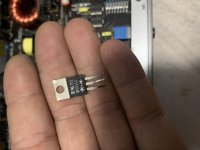
I’ve thrown away all the original transistors/rectifier but I manage to find two. And one reads IRF540 and I’ve attached a photo of the other which I’m sure is the rectifier as thats all I’ve replaced in this amplifier.
The original problem with the amplifier was that 3 of the (what is now) 3205s burned. And I replaced all the transistors and rectifier. The amplifier worked great for a few months. And then only resistors burned. Since then I’ve replaced everything everytime since this current issue of constantly burning the resistors and sometimes the transistors next to the resistors.
Do you suggest putting back in the original rectifier or a compatible part number to put in?
Attachments
Did you check the rectifier and IRF540s to see if any were defective or did you blindly replace them?
If you only have a car battery to power the amp during testing, you need to insert a 10-15 amp fuse in the B+ line for protection.
I wouldn't expect the amp to draw more than about 1.5 amps at idle.
If you only have a car battery to power the amp during testing, you need to insert a 10-15 amp fuse in the B+ line for protection.
I wouldn't expect the amp to draw more than about 1.5 amps at idle.
Sorry for late reply.
I blindly replaced them as I saw one of them blown and decided I should replace them all.
Finally got around to doing the testing.
With new gate resistors installed and removed the rectifier.
I got a 1.65 amp draw with signal sensing turned off. And amp light not on. No remote wire. When plugged into 12v. After 15 seconds
With signal sensing on. Amp light turned on. No remote wire. I got 1.75 amp draw after 15 seconds.
When the amperage draw settled touching the 8 fets. They’re are pretty warm to touch and get warmer
Last edited:
If ANY of the PS FETs failed, I'd suggest that you replace all 8 of them and carefully check the gate resistors to confirm all are within tolerance.
You also need to confirm that the drive signal is good at the leg of each FET.
I'd use the remote for testing (signal sense off). It gives better control.
When remote is initially applied, the low-voltage supply will power up. After a few seconds, the rail supply (8 FETs) and the amp will draw more current.
Everytime the gate resistors or fets failed I replaced them all to be safe. This time I only installed new resistors as the fets look fine. Just by looking it doesn’t appear any of the 8 fets have failed. How would I go about testing this signal? Would you consider the 1.75 amp draw to be excessive and calls for attention? As the fets do get warm but the sink is currently not installed either.
Check the waveforms on the gate legs of the FETs. If you don't know what they're supposed to look like, post one waveform from each bank of FETs.
- Home
- General Interest
- Car Audio
- Jl 500/1v2 keeps burning resistors