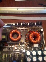
As title says, i have burned the resistors and Transistors on the Power side. I've ordered the replacement transistors and am stuck on the resistors. Can someone help me with ordering the correct resistors? The ones on the amp are burned up and am not able to read the color value. Any suggestions?
I haven't repaired a V2 but the power supply gate resistors are likely 47 ohm, 1206 (size) components.
Mouser:
71-CRCW120647R0FKEB
If you're not sure of the size of the originals, use the lead spacing of the SMD ICs. The one on the left is 1206. The one on the right is 0805.
http://www.bcae1.com/temp/ttIMG_7796b.jpg
Mouser:
71-CRCW120647R0FKEB
If you're not sure of the size of the originals, use the lead spacing of the SMD ICs. The one on the left is 1206. The one on the right is 0805.
http://www.bcae1.com/temp/ttIMG_7796b.jpg
This is the type of resistor that i'm looking for...I hope i'm not reading your post wrong. The link to the picture you posted looked like a flush mount resistor and that's not the one that is burnt on my amp.
http://209.3.61.141/iecnet/images/jpeg/RE47.jpg
Thats what the resistor looks like that is burnt up on my amp.
I hope i dont sound like an idiot. 🙂
also, Thanks for replying!
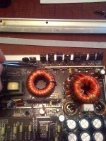
The resistor is directly infront on the Transistor...I wish i could put a picture of the items that are bad up...but there are no pictures of the JL's internals online. 🙁
http://209.3.61.141/iecnet/images/jpeg/RE47.jpg
Thats what the resistor looks like that is burnt up on my amp.
I hope i dont sound like an idiot. 🙂
also, Thanks for replying!
The resistor is directly infront on the Transistor...I wish i could put a picture of the items that are bad up...but there are no pictures of the JL's internals online. 🙁
When you say the power side, are you talking about the power supply section or the audio section? What was the original number of the transistor(s) that were burned up?
When I said power side...I ment the side with the power terminals...however, Im pretty sure it's the "audio" transistors that are bad. The transistor numbers are IRFZ44N I think...I'm at work and recalling from memory. I was able to find the correct replacement for them, just not sure what the resister values are.
The Z44Ns are the power supply FETs.
The following resistors are through-hole components similar to the one you posted. The top one is a 1/8w. The other is a 1/4w. Look at the dimensions and order the one that fits your board.
Mouser:
299-47-RC
291-47-RC
If these resistors connect to the gate leg of the IRFZ44s, the 47 ohm resistors will work.
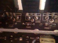
Ok, so i just took out the resistors from the board...they are burnt but would the reading from my meter be different if they were burnt? I'm getting readings randing from 70 ohms to 96 ohms from the different resistors i took off.
Here is a more detailed pic of the resistors on the board.
Here is a more detailed pic of the resistors on the board.
Attachments
JL mainly uses 1% components. For this application, either 5% or 1% would be OK. The 1% 1/8w part is:
270-47-RC
When you install the replacement resistors, install them so that there is 1/8-1/4" of clearance between the board and the body of the resistor. You'll have to determine how high they can be so that they don't touch the clip that holds the transistor in place. Having them off of the board will help prevent damage to the board if they burn again.
Ok. Thanks for the reply!! I've replaced 5 so far... I'll have to adjust the clearance now. Thanks a lot.
Well, i have all the resistors in place. I'm currently waiting on the transistors to arrive. Just for knowledge, the 500/1v2 doesn't have the clips that the 500/1 had. This one is a little different. it has a straight bar that spans the length of the board and holds the transistors against the heat thingie. 🙂
Hey, quick question...The heatsink has a thin layer of what looks to be "mica" where there is thermal compound on both sides...one that makes it stick to the heatsink and the other side makes the flush connection with the transistor...is this thin film needed? the reason i ask is because as i was trying to wipe all the old compound off of it, i accidently broke it in half.
An insulator is needed and mica is one of the better choices. Position the insulator so that the break falls between the transistors. You also need to replace the white heatsink compound.
Sounds good, i think i can do that. Thanks man for all the help...after reading so many posts...you really know your crap and have helped a lot of people.
I’m having this issue I can’t find the resistor for my 500/1 v2 amp. If anyone can point me in the right direction to purchase. I will appreciate it thank you
Please don't post in a repair thread that was started by someone else unless you are trying to help them.
Start a new thread if you need help with a repair of your own.
http://www.bcae1.com/temp/newthreaddiy01.png
Start a new thread if you need help with a repair of your own.
http://www.bcae1.com/temp/newthreaddiy01.png
- Home
- General Interest
- Car Audio
- JL 500/1v2 amp Burned Resistors