The regulated voltage for the op-amps is produced by the square yellow transformer in the center of the board.
Without remote (after just a pulse), are you waiting more than the 15 seconds that that supply will operate?
Or are you powering up normally?
Without remote (after just a pulse), are you waiting more than the 15 seconds that that supply will operate?
Or are you powering up normally?
I am doing the pulse and look for 15 seconds. I am not waiting more than 15 seconds. I do have D600 removed, so I should be safe to run it all the way up if we need data points from there.
It doesn't look like I get any switching on Q612/Q613 during that 15 seconds. I think I might have a house keeping power issue.
Is the amp set with signal-sense OFF?
Did you ever have any drive or oscillation on Q612? I don't know what 613 is.
Did you ever have any drive or oscillation on Q612? I don't know what 613 is.
Signal sense is off. Q613 an IRF540 looks like its part of that circuit. I assume the UC3843 is the driver(it doesn't have ref designator on the board). I am looking at it right now. So far, I see that I do have VCC on it for 15 seconds when I turn on the remote. Looking to see if it has output and if not I will check RT and comp.
How did you have power to the NJM319 when you posted the triangle waveform but don't have it now?
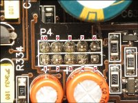
Before you start removing parts, post the DC for the pins as labeled below. Copy and paste the following list and fill in the blanks. If there is no blank space after the colon, add one between the colon and the numbers you enter. It makes it much easier to read.
Pin 1:
Pin 2:
Pin 3:
Pin 4:
Pin 5:
Pin 6:
Pin 7:
Pin 8:
Pin 9:
Pin 10:
Attachments
Im not sure what changed. Here are the numbers.
Pin 1: 1.45mV
Pin 2: 25mV
Pin 3: 11.6V only while remote is on. goes low as soon as remote is removed
Pin 4: 6.7V
Pin 5: 11.6V
Pin 6: 11.6V
Pin 7: 6.1V peak slowly drops to about 4.8V before the 15 seconds end
Pin 8: 2.5mV
Pin 9: 11.4 V
Pin 10: 1.47 mV
Pin 1: 1.45mV
Pin 2: 25mV
Pin 3: 11.6V only while remote is on. goes low as soon as remote is removed
Pin 4: 6.7V
Pin 5: 11.6V
Pin 6: 11.6V
Pin 7: 6.1V peak slowly drops to about 4.8V before the 15 seconds end
Pin 8: 2.5mV
Pin 9: 11.4 V
Pin 10: 1.47 mV
And no output on the center terminal/tab of Q612 (the one driving the transformer)?
As far as I know, Q613 is used to drain the rail voltage.
As far as I know, Q613 is used to drain the rail voltage.
I just got it to come up, but I have no clue what changed. Maybe FOD? The only thing I changed was looking at the board closely to make sure I didn't solder splash or anything, so I moved around at different angles.
Or I have an intermittent connection on preamp board causing issues it seems to make a difference if I am poking that board or not. I was just trying to remeasure P4 see if I got any different numbers.
Or I have an intermittent connection on preamp board causing issues it seems to make a difference if I am poking that board or not. I was just trying to remeasure P4 see if I got any different numbers.
I removed the preamp board, and put my flying leads on the op-amp now I am back to the I cant get the house keeping supply to switch once I put the preamp board back on.
EDIT oh wait if I push on the board just right It come up and its 28V across the op-amp
EDIT oh wait if I push on the board just right It come up and its 28V across the op-amp
I think the mating socket to P4 is worn and not making good contact. I have a lot of 2.54 10-pin sockets.
It has the same voltage on the 5-volt regulator. I can't check P4, though, because as soon as I move it at all, the input current drops, so I know the housekeeping stops.
It has the same voltage on the 5-volt regulator. I can't check P4, though, because as soon as I move it at all, the input current drops, so I know the housekeeping stops.
Ok, I changed J4 out, and now the current is no longer dropping when probe P4 and the housekeeping switching stay on.
p4 follows(pin 7 changed):
Pin 1: 6.4mV
Pin 2: 6.7mV
Pin 3: 11.6V only while remote is on. goes low as soon as remote is removed
Pin 4: 6.7V
Pin 5: 11.6V
Pin 6: 11.6V
Pin 7: 614mV
Pin 8: 8.2mV
Pin 9: 11.4 V
Pin 10: 6.4 mV
p4 follows(pin 7 changed):
Pin 1: 6.4mV
Pin 2: 6.7mV
Pin 3: 11.6V only while remote is on. goes low as soon as remote is removed
Pin 4: 6.7V
Pin 5: 11.6V
Pin 6: 11.6V
Pin 7: 614mV
Pin 8: 8.2mV
Pin 9: 11.4 V
Pin 10: 6.4 mV
Okay, back to the op-amp I changed earlier. Now that I have housekeeping power again, 1/2(bridged) actually follows pin 3, so it's about 6 mV on both. My duty cycle is not 50%.

pin 4 and 5 of the comparator

pin 4 and 5 of the comparator
- Home
- General Interest
- Car Audio
- JL 500/1 No Output Gate after 100ms (Rev 3)