That's not safe. As long as you know but others should not try this. Depending on what you connect the probe ground to, you could have 300+v on the PS ground/case.
You can use two normal probes in differential mode or an isolated scope (hand-held, like a multimeter or something like the VDS-1022I).
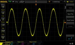
Are you referring to the noise?
I don't trust digital display scopes when it's down to small details. Can you post one from an analog scope with a CRT. Ground the scope to the main ground and probe the speaker terminals individually.
I don't trust digital display scopes when it's down to small details. Can you post one from an analog scope with a CRT. Ground the scope to the main ground and probe the speaker terminals individually.
![20181124_172508[1].jpg](/community/data/attachments/649/649751-1579273a37facfc8a0ff516d1abd2361.jpg?hash=FXknOjf6z8)
![20181124_172254[1].jpg](/community/data/attachments/649/649779-8ea4e361e55bdeb0f68f124c36e910fa.jpg?hash=jqTjYeVb3r)
![20181124_172232[1].jpg](/community/data/attachments/649/649794-4e548762341a37b67a0e0bfbef1d8906.jpg?hash=TlSHYjQaN7)
Upside-down isn't an issue.
The intermittent distortion is odd.
I don't know why people prefer LCD displays. You can see that the analog display gives a much more accurate image.
Are the images from the positive and negative speaker terminals?
If you apply remote then remove it within a few seconds and check the output drive, do you have at least 8v of drive on all outputs?
Is the drive signal going to well within 1v of ground on the falling side of the drive signal?
Set the scope to DC coupling and set the trace to the center reference before checking the signal.
- Status
- Not open for further replies.
- Home
- General Interest
- Car Audio
- JL 250/1 V2