Looking for the value of the smd resistor R852. Its on the gate of the the FET that drives the little transformer for the low voltage PS.

Also, it appears this Fet is pulsed by a LM393 thru a MM74HC. What actually creates the squarewave?
Also, it appears this Fet is pulsed by a LM393 thru a MM74HC. What actually creates the squarewave?
What version of the board do you have? The picture I have of one is different than yours. I currently have a 500/1 apart for repair, and this looks to have a 1k resistor.
R852 is a 47 ohm resistor.
The square wave is produced by a triple-inverter oscillator, if I'm not mistaken. The LM393 is simply there to enable the oscillator. Pin 6 of the 74HC02 must be low for the oscillator to produce output.
To upload photos click the following:
Go Advanced
Manage Attachments
Browse
Upload
Repeat as necessary
Preview post to see how the post will look.
Click Submit Reply to send it to the forum.
Can you order from JL? Is that what you are suggesting.
Should I be able to get the square wave prior to inserting this low voltage PS Fet? The fet shorted and I assume took out the gate resistor R852.
So I am trying to trace what originates the drive square wave for this fet.
The output driver boards and the output fets are not on the main board yet.
Should I be able to get the square wave prior to inserting this low voltage PS Fet? The fet shorted and I assume took out the gate resistor R852.
So I am trying to trace what originates the drive square wave for this fet.
The output driver boards and the output fets are not on the main board yet.
JL will provide absolutely no support.
I'm suggesting that you use the markings to get the part number to order parts from a reputable distributor (NOT ebay).
You should get the 74HC02 to oscillate if you bridge terminals 6 and 7 on it.
I'm suggesting that you use the markings to get the part number to order parts from a reputable distributor (NOT ebay).
You should get the 74HC02 to oscillate if you bridge terminals 6 and 7 on it.
It does now. There was an open resistor.
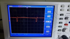
Pin 6 is hi so I bridged pin 6 & 7 and got this waveform.

Pin 6 is hi so I bridged pin 6 & 7 and got this waveform.

Reread. When right, the image will open in a popup window with an option to enlarge in the lower left when the image is larger than the display.
Last edited:
OK installed FET and it worked - for a while. Looks like there is an intermittent problem where the 2 transistors driving the gate are not passing the drive signal. The drive is there on the base of each transistor. The emitters of both are passing 5vdc which is not allowing the fet to turn off. The collector of one transistor has B+ and the other has 0v.
Could the driver with B+ on the collector be passing the 5v? It checks out in circuit on a diode check, but I haven't pulled it out of circuit yet.
Could the driver with B+ on the collector be passing the 5v? It checks out in circuit on a diode check, but I haven't pulled it out of circuit yet.
The collector of the PNP driver should be directly connected to ground. If the bases are going to ground but the emitters aren't following to ground, the PNP driver is defective.
Re-soldered the 10 pin connector on the pre-amp board and it seems to have solved the intermittent loss of drive on the low power supply fet. If I wiggled the preamp board on the remote-in area the fet would lose drive signal and get a flat 5vdc drive (which is what probably destroyed the fet in the first place).
Back to this amp. It was worked fine for a couple of weeks but now has blown the low voltage ps fet again.
Something intermittent with the drive to this fet. I can only get the U801 (74HC02) to output by shorting pin 6 & 7. Pin 3 of the 393 is at 5 volts and outputting 5v thru pin 1 to pin 6 of the 74HC02. Pin 6 needs to be low.
Any ideas?
Something intermittent with the drive to this fet. I can only get the U801 (74HC02) to output by shorting pin 6 & 7. Pin 3 of the 393 is at 5 volts and outputting 5v thru pin 1 to pin 6 of the 74HC02. Pin 6 needs to be low.
Any ideas?
If you didn't completely desolder and then resolder the connector pins, that could cause the intermittent problem. It may be necessary to remove the header, scrape the pins, re-tin and then resolder. With the header out, you should flood the vias and desolder.
Did you use a logic level FET when you replaced the FET?
Did you use a logic level FET when you replaced the FET?
- Home
- General Interest
- Car Audio
- JL 1000/1 R852 Value??