I have a 1000/1 on the bench which shorted a pair of output FETs, but replacing them didn’t solve the problem. When it turns on, it makes a shrieking sound...
After some poking around with the scope I realized that all the output gates have drive, but the on time isn’t balanced between the high and low side like I would expect. The PWM is unbalanced all the way back to the comparator. Probing pin 5 of U511 shows the normal sawtooth coming from the 555 timer as expected, and pin 4 is 1.7v. Sure seems like pin 4 should be higher, like maybe around 2.5v?
Can anyone verify what pin 4 should be, and if that’s what’s wrong, what sets the DC on that pin? Offset pot had no effect.
That's to be expected since this removed all compensation for errors in the output. This is just to check the drive signal at 50% duty cycle (maybe not exactly 50%).
So it has possibly something wrong with the feedback end of things? That was my first though as well, but curiously the offset pot has no effect.
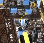
Before you added the jumper, did the amp produce audio?
Are all drive signals at the gates of the output FETs (before rail voltage develops) clean with the jumper?
I can't keep up with who has the tutorial (especially when no one uses their real names) but if you have the tutorial, the jumper and other information is on the JL1000 page.
Are all drive signals at the gates of the output FETs (before rail voltage develops) clean with the jumper?
I can't keep up with who has the tutorial (especially when no one uses their real names) but if you have the tutorial, the jumper and other information is on the JL1000 page.
Can't test for audio with unbalanced drive, it makes a horrible screeching and draws excessive current...
Drive is clean, just long duty on one half and short on the other guessing the output stage is shooting through slightly causing the excessive current.
Drive is clean, just long duty on one half and short on the other guessing the output stage is shooting through slightly causing the excessive current.
Looking at the input and output of the op-amps that feed the op-amp you jumped, do the inputs agree with the output?
Are all of the supply voltage present and correct on those op-amps?
Are all of the supply voltage present and correct on those op-amps?
Actually that OPAMP itself (U517) isn't making sense, both inputs are very near zero (.007vdc) and it's putting out -1.4vdc. Think I found the culprit?
Good +/-15 on the opamps
Good +/-15 on the opamps
All the op-amp is working to do it to make its inputs match. The output of the op-amp has to drive through all of the drive circuit, through the outputs and the other two op-amps that drive this op-amp. Anything in that circuit can make a difference in the output of that op-amp and -1.4v could be right if the output of the amp is at 0v (across terminals).
What's the DC voltage across the speaker terminals?
Does the screeching ever change with any combination of the preamp switches?
Does it screech with no RCAs plugged in?
What's the DC voltage across the speaker terminals?
Does the screeching ever change with any combination of the preamp switches?
Does it screech with no RCAs plugged in?
the other two op-amps that drive this op-amp
I only found one other connection to it, which goes over to an OPAMP output near the offset pot. I’m beginning to think something in the offset circuit fried when the output stage blew, because the drive should be balanced (duty cycle wise) before the main supply comes up and it’s not. And because the drive is imbalanced, the moment the output stage sees rail voltage the output inductors start screeching because of the cross conduction/shoot through.
With respect to ground one side of the output stage is making nearly 70v while the other is down near 30, when both should be right around 50. I’m going to poke around the offset circuit tonight and see if anything jumps out at me there.
There is no guarantee that the duty cycle without rails will be 50%, even with the 6-7 jumper. That will vary by the amplifier.
Unless I'm mistaken, there are two sections for the feedback circuit. One for the DC part of the signal and that's connected to the DC pot. The other section is for the AC part of the signal. Those two outputs (DC and AC) are mixed and sent back to the pot that you jumped. You need to look at the inputs and the outputs to see if the output is what is should be for the signals being fed into that section of the op-amps.
Unless I'm mistaken, there are two sections for the feedback circuit. One for the DC part of the signal and that's connected to the DC pot. The other section is for the AC part of the signal. Those two outputs (DC and AC) are mixed and sent back to the pot that you jumped. You need to look at the inputs and the outputs to see if the output is what is should be for the signals being fed into that section of the op-amps.
Checked all three opamps near the offset pot, no voltage at any of the inputs and the outputs register 0 as well so I think the problem does not lie there. This is just with the standby supply only BTW (pulsing the remote). Any idea which opamp is is charge of AC feedback?
It will have two signal lines running to it from the output and you will see matched pairs of values for the two inputs. I don't know if it's going to be the AC half of the circuit because (in the 500, at least, the circuit is AC coupled (series capacitor).
What is the exact voltage on the 3 pins (5, 6 and 7) of the op-amp you put the jumper on?
What is the exact voltage on the 3 pins (5, 6 and 7) of the op-amp you put the jumper on?
1.7v at the comparator input
I did follow the output of U517 and it appears to be connected to a voltage divider consisting of a pair of resistors that are fed directly from the 5v regulator, so in essence U517 acts as a sink which tends to pull down on the voltage divider the more negative the output swings. So the more negative the output of U517 is, the lower the voltage seen at the input of the comparator will be, and thus the shorter it’s duty cycle at the output will become. I proved this by looking at the output of the comparator while shorting U517 like you mentioned in post #2, and the duty increases when shorting those 2 points.
I think I will try replacing U517 when I get home today. I work full time still, this is just a hobby for me so I sometimes won’t have updates for several days.
- Home
- General Interest
- Car Audio
- JL 1000/1 PWM comparator