Hi everyone, I am new to this forum and new to valve amp design so please be kind, haha.
I have recently brought some ECC83S's from JJ as stated in the title. The question I have is about the vagueness of the datasheet. This can be found here.
http://www.drtube.com/datasheets/ecc83s-jj2003.pdf
I am looking for the Vgk, that my text book for this says should be around -1V. Is this the Ug characteristic on the datasheet and if it is does this not sound a bit low?
Any help with this (or biasing these tubes in general would be very much appreciated.
Thanks
Mash
Last edited:
Download this document first:
http://www.tubebooks.org/Books/York_Amplifiers.pdf:
And then begin reading from page 36.
There is a comprehensive information about operating point, biasing and load line.
http://www.tubebooks.org/Books/York_Amplifiers.pdf:
And then begin reading from page 36.
There is a comprehensive information about operating point, biasing and load line.
Hi artosalo,
Thanks for the document, I think this one could become useful in the near future.
If I am right does it mean that the datasheet is saying that the typical grid voltage would be -2V, where the minimum would be -1V?
Thanks again,
Matt
Thanks for the document, I think this one could become useful in the near future.
If I am right does it mean that the datasheet is saying that the typical grid voltage would be -2V, where the minimum would be -1V?
Thanks again,
Matt
without knowing your Ip and Vp, Vgk is a guessing game...
with your data sheet, you can look at the plate curves for that value...
it is all there...
with your data sheet, you can look at the plate curves for that value...
it is all there...
...If I am right does it mean that the datasheet is saying that the typical grid voltage would be -2V, where the minimum would be -1V?
That Ug = -2 V is a good rule of thumb, but in practise I have noticed that ECC83 works fine and even with lower distortion when Ug = -1...-1.5 V.
Hi everyone, I am new to this forum and new to valve amp design so please be kind, haha.
I have recently brought some ECC83S's from JJ as stated in the title. The question I have is about the vagueness of the datasheet. This can be found here.
http://www.drtube.com/datasheets/ecc83s-jj2003.pdf
I am looking for the Vgk, that my text book for this says should be around -1V. Is this the Ug characteristic on the datasheet and if it is does this not sound a bit low?
Any help with this (or biasing these tubes in general would be very much appreciated.
Thanks
Mash
The datasheet is not vague. It's clear as day 😀
There is no single operating point at which a ECC83 or other tube should be biased. It's dependent on many factors. For normal conditions, you can do with a 'ballpark' voltage which should allow the tube to swing the grid positive and negative in equal amounts within a somewhat linear region. If you want to build an FX box, distortion pedal or run the tube hotter/cooler, you can vary the bias both ways with different outcome.
The Ug=-2V is pretty common, but 1V or 1.5V, depending on the input signal is, is fine as well.
Last edited:
The datasheet is not vague. It's clear as day 😀
Yes, but the problem is that most of the JJ ECC83S that I've measured were nowhere near the datasheet curves. 🙂
Yes, but the problem is that most of the JJ ECC83S that I've measured were nowhere near the datasheet curves. 🙂
Interesting. What did you measure? Different transconductance? Steaper curves? I know heater current consumption can vary wildly.
Can we try to give straight answer, just once at any forum? 🙂
.
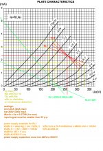
With present JJ datashhet
I would go for the
Rload from
48K (for gain about 50 X), to 122K (for gain about 73 X)
load line for JJ ECC83 model. For minimum or no distortion.
That is valid only in linear region with settings for working point
at
Ug=-1.5V
Io=2.2mA
Ua=260V
and signal in range of 2V p-p. Or smaller.
.
With present JJ datashhet
I would go for the
Rload from
48K (for gain about 50 X), to 122K (for gain about 73 X)
load line for JJ ECC83 model. For minimum or no distortion.
That is valid only in linear region with settings for working point
at
Ug=-1.5V
Io=2.2mA
Ua=260V
and signal in range of 2V p-p. Or smaller.
Attachments
😕Why did you draw the operating point that high up? They should be on the loadlines.
Edit: I see, you were deriving optimum HT voltages(?)
Edit: I see, you were deriving optimum HT voltages(?)
Last edited:
Can we try to give straight answer, just once at any forum? 🙂
.
With present JJ datashhet
I would go for the
Rload from
48K (for gain about 50 X), to 122K (for gain about 73 X)
load line for JJ ECC83 model. For minimum or no distortion.
That is valid only in linear region with settings for working point
at
Ug=-1.5V
Io=2.2mA
Ua=260V
and signal in range of 2V p-p. Or smaller.
Your load lines require some 400...450 V as +Ub !!
Is this really your intention ?
Actually NOT
please see the jpeg...
the Vbattery power supply for the stage is 380V cca for the load of standard 51K
with gain little more of about 50 X.
With a bypassed Rk of 680ohms - 682ohms, say 100uF to 220uF.
Which is not so huge and will cover the 450V standard value of C in power supply.
AND larger input range voltage up to 2V p-p without distortion.
All that in safe range of maximum given values for tube.
And off course in linear region of opperation.
That means that Cureent and also voltage values will remain almost equal in all range of load line... Not only current like usual.
🙂
Thanks guys, indeed all I need is straight answers, I am new to this as stated and may ask silly questions but hey how else am I going to learn?
Funk1980, the reason I said the datasheet was vague was to do with the fact that the text book I am reading says it should state a minimum Vgk where I can not see this on the JJ datasheet, maybe I am missing something, or can we derive this from other values?
Zoran, thanks for your jpeg, I have a couple of questions. What did you use to make it, is it a simulating software or just a spreadsheet? The other question is that if I place the voltage at 260V and chose RL1 then does the voltage not swing up to 310V, ten volts more than the limit of 300V on the datasheet (or up to 330V if RL4 chosen)?
Thankyou very much for your help everyone.
Few datasheets give a minimum Vgk for low grid current. This is partly because the actual value varies from sample to sample, and with ageing. Assume it will be somewhere between -0.5V and -1.5V and design accordingly, especially if the source has high impedance.
Load lines can only 'swing' above the supply rail if an anode choke is used. Brief excursions above the maximum anode voltage are usually fine.
Load lines can only 'swing' above the supply rail if an anode choke is used. Brief excursions above the maximum anode voltage are usually fine.
Mashly I dint use any additional tool
except paper and pen (photoshop in this case 🙂)
It is a static analysis for classic triode gain stage.
which is pretty sufficient to form a operating points.
Goal is to establish the minimum distortion and optimum settings.
.
With that datas, next step could be simulation.
No point for the sim if dont know what is really happening...
.
Voltage will NOT swing to 310 or 330V.
Because we recognise 3 voltage values:
-Ug = negative biasing voltage, absolite value is from ground to Katode @ Rk resistor
Ua = Anode voltage, that is votage between A and K of tube. In this case is always 260V
VRload = dc voltagew drop @ given resistor, with respect to curent flow, Io=2.2mA
Vb = V battery, or power supply stage voltage.
.
Like on the jpeg again,
Vb = I-UgI + Ua + VRload
.
So with different Load lines, change will ocure in Voltage across Rload resistor
and then impact the Vb total voltage.
Ua still remains the same value...
🙂
It is often better to assume a suitable supply voltage then draw load lines from there. It will usually be found that lowest distortion and highest gain come from a fairly high anode resistor, especially for ECC83/12AX7.
- Status
- Not open for further replies.
- Home
- Amplifiers
- Tubes / Valves
- JJ ECC83S Biasing conditions