I’d very much like to have an audio file based on Julian Dunn’s exact description for jitter testing (http://www.nanophon.com/audio/diagnose.pdf). As far as I know this file isn’t available for downloading. I’ve come to understand that such a signal would be possible to create with a program like MATLAB. However after some intense browsing a came to the conclusion that the scripting is beyond me. I’ve copied the original explanation from Dunn’s paper below. Maybe somebody is willing to figure it out.
Kind regards,
Merlijn
Kind regards,
Merlijn
A test signal has been developed in order to stimulate worst-case levels of data-jitter. This signal has
two components. The first is an un-dithered square wave with a period of 4 samples. A cycle of this
is shown here in hexadecimal notation (hex):
C00000 C00000 400000 400000
On conversion to analogue at a sample rate of 48kHz this signal would produce a sine wave with an
amplitude of -3.01dBFS at 12kHz.
This is added to an undithered 24 bit square wave of amplitude 1 least significant bit (1 LSB) and dc
offset of -1/2 an LSB. This square wave is repeated at low frequency. In the case of the signal used
in these tests a rate of 250Hz was selected. This adds an undithered square wave of amplitude -
144dBFS and a negative dc offset of -150dBFS. The two values used for this square wave are 0 and
-1 (FFFFFF).
The combination of these signals results in the following 192 sample cycle of 24-bit data values:
C00000 C00000 400000 400000 (x 24) BFFFFF BFFFFF 3FFFFF 3FFFFF (x 24)
The low frequency coherent alternation in the values of the 22 LSBs produces strong jitter spectral
components at the repetition rate and its odd harmonics. A low frequency was used to stimulate jitter
at a frequency that will not be attenuated significantly by a receiver clock recovery circuit. The high
frequency component was selected for convenience when making jitter measurements of DACs; this
is discussed in a later section.
OK, here's a zip file (down at the bottom), it contains a file called jitter.exe. If you run it it will ask you to press a key to start, it takes a while to run, then it'll ask you to press a key again to indicate that it's done.
It'll create a file in the same directory, jitter.wav, of 17,280,044 bytes, the .wav header and one minute of stereo sound @ 48ksamples, 24 bit resolution.
I've looked at the file with a hex editor, it looks OK to me, there's a mixture of Big- and Little-endian data in there, God knows what Microsoft were up to.
Here's the code, it compiles under Microsoft QC25, if there are any problems you can look and see if you can see any errors, I haven't attempted to debug the output in any way apart from look at it in the hex editor, I haven't tried to run it.
/*******************************************\
* jitter.c *
* 14/02/2011 *
* wakibaki *
\*******************************************/
#include <stdio.h>
#include <io.h>
#include <fcntl.h>
#include <ctype.h>
void main();
void main()
{
FILE *fp;
long length, fileptr;
unsigned char d;
int i;
printf("\jitter\n\n");
printf("Press a key to continue...\n");
getch();
length=15000;
if((fp=fopen("jitter.wav","wb"))!=NULL){
d='R'; /* Chunk ID*/
fputc(d,fp);
d='I';
fputc(d,fp);
d='F';
fputc(d,fp);
d='F';
fputc(d,fp);
d=0x24; /* Chunk Size, 36+No of samples */
fputc(d,fp);
d=0xAC;
fputc(d,fp);
d=0x07;
fputc(d,fp);
d=0x01;
fputc(d,fp);
d='W'; /* Format */
fputc(d,fp);
d='A';
fputc(d,fp);
d='V';
fputc(d,fp);
d='E';
fputc(d,fp);
d='f'; /* SubChunk 1 ID*/
fputc(d,fp);
d='m';
fputc(d,fp);
d='t';
fputc(d,fp);
d=' ';
fputc(d,fp);
d=0x10; /* SubChunk 1 size */
fputc(d,fp);
d=0x00;
fputc(d,fp);
d=0x00;
fputc(d,fp);
d=0x00;
fputc(d,fp);
d=0x01; /* Audio Format*/
fputc(d,fp);
d=0x00;
fputc(d,fp);
d=0x02; /* MumChannels */
fputc(d,fp);
d=0x00;
fputc(d,fp);
d=0x80; /* Sample rate */
fputc(d,fp);
d=0xBB;
fputc(d,fp);
d=0x00;
fputc(d,fp);
d=0x00;
fputc(d,fp);
d=0x00; /* Byte rate */
fputc(d,fp);
d=0x65;
fputc(d,fp);
d=0x04;
fputc(d,fp);
d=0x00;
fputc(d,fp);
d=0x06; /* Block Align */
fputc(d,fp);
d=0x00;
fputc(d,fp);
d=0x18; /* Bits Per Sample */
fputc(d,fp);
d=0x00;
fputc(d,fp);
d='d'; /* SubChunk2 ID */
fputc(d,fp);
d='a';
fputc(d,fp);
d='t';
fputc(d,fp);
d='a';
fputc(d,fp);
d=0x00; /* SubChunk2 Size */
fputc(d,fp);
d=0xAC;
fputc(d,fp);
d=0x07;
fputc(d,fp);
d=0x01;
fputc(d,fp);
for(fileptr=0;fileptr<length;fileptr++){
for(i=0;i<24;i++){
d=0x00; /* Data - Little Endian */
fputc(d,fp);
d=0x00;
fputc(d,fp);
d=0xC0;
fputc(d,fp);
d=0x00;
fputc(d,fp);
d=0x00;
fputc(d,fp);
d=0xC0;
fputc(d,fp);
d=0x00;
fputc(d,fp);
d=0x00;
fputc(d,fp);
d=0xC0;
fputc(d,fp);
d=0x00;
fputc(d,fp);
d=0x00;
fputc(d,fp);
d=0xC0;
fputc(d,fp);
d=0x00;
fputc(d,fp);
d=0x00;
fputc(d,fp);
d=0x40;
fputc(d,fp);
d=0x00;
fputc(d,fp);
d=0x00;
fputc(d,fp);
d=0x40;
fputc(d,fp);
d=0x00;
fputc(d,fp);
d=0x00;
fputc(d,fp);
d=0x40;
fputc(d,fp);
d=0x00;
fputc(d,fp);
d=0x00;
fputc(d,fp);
d=0x40;
fputc(d,fp);
}
for(i=0;i<24;i++){
d=0xFF;
fputc(d,fp);
d=0xFF;
fputc(d,fp);
d=0xBF;
fputc(d,fp);
d=0xFF;
fputc(d,fp);
d=0xFF;
fputc(d,fp);
d=0xBF;
fputc(d,fp);
d=0xFF;
fputc(d,fp);
d=0xFF;
fputc(d,fp);
d=0xBF;
fputc(d,fp);
d=0xFF;
fputc(d,fp);
d=0xFF;
fputc(d,fp);
d=0xBF;
fputc(d,fp);
d=0xFF;
fputc(d,fp);
d=0xFF;
fputc(d,fp);
d=0x3F;
fputc(d,fp);
d=0xFF;
fputc(d,fp);
d=0xFF;
fputc(d,fp);
d=0x3F;
fputc(d,fp);
d=0xFF;
fputc(d,fp);
d=0xFF;
fputc(d,fp);
d=0x3F;
fputc(d,fp);
d=0xFF;
fputc(d,fp);
d=0xFF;
fputc(d,fp);
d=0x3F;
fputc(d,fp);
}
}
fclose(fp);
}
else{
printf("\nError opening files...\n");
exit(1);
}
printf("\jitter\n\n");
printf("Press a key to continue...\n");
getch();
exit(0);
}
w
Attachments
On second thought, would it be possible to also create a 16 bit 44.1 kHz version using the same method. I’ve come to understand that the following parameters (https://ccrma.stanford.edu/courses/422/projects/WaveFormat) need to be changed:
*This cycle rate or number of samples should stay unaltered to maintain the 4/1000 and 1/4 sample rate frequency ratio.
Kind regards,
Merlijn
- ChunkSize (10584036 or A17FE4 HEX)
- SampleRate (44.1 kHz or AC44 HEX)
- ByteRate (176400 or 2B110 HEX)
- BlockAlign (4 or 4 HEX)
- BitsPerSample (16 or 10 HEX)
- Subchunk2Size (10584000 or A17FC0 HEX)
- Data (C000 C000 4000 4000 (x 24) BFFF BFFF 3FFF 3FFF (x24) at 192 sample cycle*)
*This cycle rate or number of samples should stay unaltered to maintain the 4/1000 and 1/4 sample rate frequency ratio.
Kind regards,
Merlijn
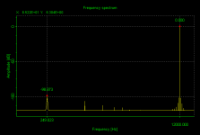
The added fake "jitter" was at the LSB in a 24 bit signal. I don't know how did you convert THAT to 16 bit...It seems to work. Here is an FFT. I had to convert it to 16 bits, but you get the idea.
And yet this way of working produces bit accurate results that comply with Dunn’s original paper. I’ve downloaded at least one version of the 16 bit test signal claimed to be the “one”. But closer inspection using a hex editor shows small imperfections. I for one hope that this method can be used to create a 16 bit version.
Regards,
Merlijn
Regards,
Merlijn
I don't think it can be done. The whole ideea is based on using a "smaller" 24bit step to simulate the jitter of the "bigger" 16bit signal. You need to feed that 24 bit as a 16 bit signal to the receiver to be perceived as jitter.
If you have the same 16 bit for both, you will end up with just regular signal, and that will NOT be seen as jitter by the receiver.
If you have the same 16 bit for both, you will end up with just regular signal, and that will NOT be seen as jitter by the receiver.
The added fake "jitter" was at the LSB in a 24 bit signal. I don't know how did you convert THAT to 16 bit...
I had to convert to 16 bit to read it in my FFT sotware, as it did not like the 24 bit version. Does not mean you have to use it that way.
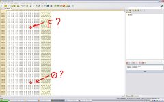
I took the liberty of looking at 24 bit wave file with a hexadecimal editor. The only thing I’ve noticed is that at the repetitive transitions from “C00000 C00000 400000 400000” to “BFFFFF BFFFFF 3FFFFF 3FFFFF” and vice versa, shouldn’t the last hexadecimal be respectively F instead of 0 and F instead of 0? I’ve attached a screen dump to illustrate what I mean. Correct me if I’m wrong.
Regards,
Merlijn
Regards,
Merlijn
Attachments
Well, that's not what it says in your quote:
I can modify it to correspond with what you suggest, but that's not how I read it, and it's not how I understand it from the foregoing description:-
The first is an un-dithered square wave with a period of 4 samples. A cycle of this is shown here in hexadecimal notation (hex):
C00000 C00000 400000 400000
This is added to a... 24 bit square wave of amplitude 1 least significant bit (1 LSB) and dc offset of -1/2 an LSB. This square wave is ... 250Hz. The two values used for this square wave are 0 and -1 (FFFFFF).
C00000 + 0 = C00000
400000 + 0 = 400000
C00000 - 1 = BFFFFF
400000 - 1 = 3FFFFF
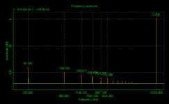
...Yes, Pano, a combination of having a number of similar files and some Valentine's Day distractions. Somehow I managed to overwrite the new with the original. Hopefully this one is correct. This one is 48ksamples which preserves the original frequencies of 12kHz and 250Hz. Altering the sample rate to 44k1 changes the frequencies to 11,025Hz and 229.6875Hz, which are integer fractions of 44k1. Trying to keep the frequencies unchanged results in considerable complication and will anyway produce a result quite far removed from the original intent. A 44k1 file using the frequencies 11,025Hz and 229.6875Hz follows...
w
I can generate the files with the swapped F's and 0's without too much extra effort, so I'll do it and you can mess around with them.
The combination of these signals results in the following 192 sample cycle of 24-bit data values:
C00000 C00000 400000 400000 (x 24) BFFFFF BFFFFF 3FFFFF 3FFFFF (x 24)
I can modify it to correspond with what you suggest, but that's not how I read it, and it's not how I understand it from the foregoing description:-
The first is an un-dithered square wave with a period of 4 samples. A cycle of this is shown here in hexadecimal notation (hex):
C00000 C00000 400000 400000
This is added to a... 24 bit square wave of amplitude 1 least significant bit (1 LSB) and dc offset of -1/2 an LSB. This square wave is ... 250Hz. The two values used for this square wave are 0 and -1 (FFFFFF).
C00000 + 0 = C00000
400000 + 0 = 400000
C00000 - 1 = BFFFFF
400000 - 1 = 3FFFFF
...Yes, Pano, a combination of having a number of similar files and some Valentine's Day distractions. Somehow I managed to overwrite the new with the original. Hopefully this one is correct. This one is 48ksamples which preserves the original frequencies of 12kHz and 250Hz. Altering the sample rate to 44k1 changes the frequencies to 11,025Hz and 229.6875Hz, which are integer fractions of 44k1. Trying to keep the frequencies unchanged results in considerable complication and will anyway produce a result quite far removed from the original intent. A 44k1 file using the frequencies 11,025Hz and 229.6875Hz follows...
w
I can generate the files with the swapped F's and 0's without too much extra effort, so I'll do it and you can mess around with them.
Attachments
a combination of having a number of similar files and some Valentine's Day distractions.
")

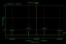
Oddly, I don't see jitter added, just the 229.x Hz square wave. No sidebands on the fundamental. Is that to be expected?
Sorry, I can't comment on that, I'll read the article, I haven't done that yet.
It's a bit of an odd thing to do, put a square wave into a DAC, particularly at half the Nyquist frequency, there are obviously loads of harmonics there which you would expect to alias down into the passband. Normally any signal would be low-pass filtered to exclude any components above 22.5kHz.
Anyway I didn't pay any attention to that, I just set out to create the file according to the specification as I read it.
w
- Status
- This old topic is closed. If you want to reopen this topic, contact a moderator using the "Report Post" button.
- Home
- Source & Line
- Digital Source
- Jitter Test Signal (J-test Signal) with MATLAB