If I understantand all this correctly, then:
- Leakage inductance must be high and interwinding capacitance must be very low to prevent common mode noise coupling into signal?
- Bandwith must also be low to prevent common mode noise coupling into signal?
- How much bandwith is needed? Is 2.8 Mhz enough? More?
- What is more important, good performance in low or high frequency bandwith?
- To limit bandwith even further, then DC blocking cap should be low in value too?
- Is 10nF (as suggested per datasheets) too much, should value be even smaller, maybe 1 nF?
- Small ceramic caps are bad for audio, they are microphonic, causing audible distortion & sibilance. Teflon is the best. Will there be audible difference is Teflon cap is used? Or should be MKP cap enough?
- Is power supply important? Can anything be improved with better power supply or is PSRR of DAC chip and logic chips enough?
Last edited:
CM noise a more pressing issue than jitter
NO..... CM is a major source of jitter. There is no common mode with toslink
and well done Toslink can have less jitter than many coax SPDIF links.
What would be great then would an example of well done Toslink? - I'd love to experiment.
Yes, but do you know of a DAC where there the only difference between Toslink & Coaxial SPDIF is going to be the CM noise i.e the jitter is controlled & common?
No, I know of very few DACs with Toslink - it does tend to be associated with the 'low end' because of its reputation for poor jitter (completely justified). Poorly designed DACs don't fix Toslink jitter nor do they address CM noise on SPDIF. A DAC for your experiment would need to be specially designed 😀
If I understantand all this correctly, then:
- Leakage inductance must be high and interwinding capacitance must be very low to prevent common mode noise coupling into signal?
No, common mode noise is common mode, by definition. So its already present on both signal and ground. Higher leakage inductance and lower interwinding capacitance can (and I believe does) reduce CM noise being induced into DAC circuit ground.
- Bandwith must also be low to prevent common mode noise coupling into signal?
No, see above. 'Coupling into' is a red herring.
- How much bandwith is needed? Is 2.8 Mhz enough? More?
Read the paper by Hawksford and Dunn. Its on Hawksford's website.
<snippage, let's deal with first things first 🙂 >
yes, I stand corrected, it should be "...induced from primary to secondary".
Then higher leakage inductance and lower interwinding capacitance are reducing common mode noise being induced into DAC ground, is this correct?
But then bandwith must also be very low, to prevent high frequency noise being induced on secondary winding and DAC ground. High bandwith is bad and low interwinding capacitance will help reducing bandwith of the transformer, is this correct?
If you mean "Is The AESEBU / SPDIF Digital Audio Interface Flawed ?" article, I found no mention of required bandwith. I found only that ...digital links should be designed with bandwiths well above 6 MHz. Then 12 MHz (6 MHz doubled) should be enough?
What about other questions?
.....
If you mean "Is The AESEBU / SPDIF Digital Audio Interface Flawed ?" article, I found no mention of required bandwith. I found only that ...digital links should be designed with bandwiths well above 6 MHz. Then 12 MHz (6 MHz doubled) should be enough?
.........
Does it not say that 10 - 90% rise & fall times of less than 10nS require a bandwidth of 35MHz?
yes, I stand corrected, it should be "...induced from primary to secondary".
I'd prefer 'coupled from primary to secondary' myself 🙂
Then higher leakage inductance and lower interwinding capacitance are reducing common mode noise being induced into DAC ground, is this correct?
Yep.
But then bandwith must also be very low, to prevent high frequency noise being induced on secondary winding and DAC ground. High bandwith is bad and low interwinding capacitance will help reducing bandwith of the transformer, is this correct?
Do you mean differential mode bandwidth, or common mode?
If you mean "Is The AESEBU / SPDIF Digital Audio Interface Flawed ?" article, I found no mention of required bandwith. I found only that ...digital links should be designed with bandwiths well above 6 MHz. Then 12 MHz (6 MHz doubled) should be enough?
My memory of that paper might not be perfect (ha) but I seem to recall that it has some kind of mathematical treatment of how bandwidth and jitter are related. So the bandwidth you choose will be pretty strongly influenced by how much jitter you're prepared to accept. Jitter here being inter-symbol interference - modulating the edge timings according to data.
What about other questions?
Your other questions? Let's see:
- What is more important, good performance in low or high frequency bandwith?
Here's one I can't understand. Are you asking about what's the lowest and highest frequency we should pass over SPDIF?
- To limit bandwith even further, then DC blocking cap should be low in value too?
No, from what I've read quite the opposite. We should aim for the transformer to limit the LF point, not any coupling caps. High value caps are cheap, transformers with good LF performance are not. So choose coupling caps which give LF points at least a decade below that of the trafo.
- Is 10nF (as suggested per datasheets) too much, should value be even smaller, maybe 1 nF?
See above - the opposite direction seems better to me. Consider 1uF.
- Small ceramic caps are bad for audio, they are microphonic, causing audible distortion & sibilance.
Not all ceramics, no. NP0 ceramics are as close to being a perfect capacitor as I've found for high frequency applications. Z5U and X5R are fairly poor from the point of view of microphony though.
Teflon is the best. Will there be audible difference is Teflon cap is used? Or should be MKP cap enough?
Best is no cap at all. I don't listen to cap varieties myself so have nothing to offer here.
- Is power supply important? Can anything be improved with better power supply or is PSRR of DAC chip and logic chips enough?
Power supply needs to be considered as a whole with layout, decoupling and grounding issues. So don't throw a low-noise power supply at a circuit with decoupling problems, rather fix the decoupling. That's a far better use of resources. Sure, power supplies matter, definitely.
Obtaining good common-mode rejection requires a minimal coupling capacitance between primary and secondary. A transformer with an electrostatic shield between its primary and secondary offers higher common-mode rejection than a transformer without a shield.
A high leakage inductance, however, impacts on the transformed signal (magnitude and pulse shape) because it stores uncoupled energy and acts like a series inductance.
A high leakage inductance, however, impacts on the transformed signal (magnitude and pulse shape) because it stores uncoupled energy and acts like a series inductance.
Although CM noise is interesting & it would be great to try to tease out it's contribution to bad sonics in the digital audio world, maybe we can focus a bit more on jitter & use the Audiophileo 2 which offers a feature that is interesting but I haven't seen anybody reporting on it - the ability to increase the jitter on the SPDIF output. Now, I don't know how this is implemented but it strikes me as a useful way of investigating the sonic effect of jitter & the level at which it can be heard. Now I know this single jitter number is a very crude measure of jitter & it requires more detail as to type & spectrum of jitter but it could be useful!
You'll need a DAC (obviously), a signal generator (your choice) and a few resistors.
Online Sketch: Untitled Sketch by Anonymous Author
You can simply inject some signal into the DAC clock line, that will translate into jitter directly. You can use any signal, noise, sinus, even the output of the DAC itself (then you'll get correlated jitter). Calculating the amount of jitter that you actually added could be a bit difficult though.
You guys need to do some research on the fundamentals before you waste anymore time speculating on the fine points or something I think most of you have never listened to, built, or measured and listened to different permutations ( logic families, bandwidth, digital cables, impedance matching, AC coupling) If you actually want learn something:
A Transport of Delight: CD Transport Jitter | Stereophile.com
The Jitter Game | Stereophile.com
Jitter & the Digital Interface | Stereophile.com
http://amorgignitamorem.nl/Audio/Ji...ions due to jitter on digital audio 26_50.pdf
Digital Audio Application Notes Jitter and Its Effects | Benchmark Media
( note further reference in article)
Training & Events: Jitter Analysis and Injection | Agilent
How curious that you would link us to some writings of Robert Harley to learn from. Would you please also provide us with a link to inform us of some of the products he's designed?
I like this Japanese article. They simulate random jitter in software by modifying the original waveform, using the original sample rate. This looks like a model for what happens in a non-oversampling DAC. OK.
No details are given on this digital processing. After processing, the data has more than 16 bits word length, but they don't seem to mention if it was converted back to 16 bits (probably it was) and how (which dither, truncation, etc).
No details are given about the simulated jitter, only that it is random, and its RMS value : no mention of spectrum, integration bandwidth, phase noise, probability distribution of the random function they used, etc.
Given the rarity of non-oversampling DACs, I'd tend to assume than most DACs in the experiment were either oldskool oversampling (4-8x + multibit converter) or sigma-delta (very high oversampling + low-bit converter). The only relevant jitter is the one on the D/A converter sample clock, but the simulated jitter is applied at the original sample rate.
So, this article shows that a very large amount of an unspecified kind of random jitter is not audible on music played on something that would look like a non-oversampling DAC.
As usual it is easier to measure what is measurable rather than what is relevant 😀 (see: THD)
The article by Benchmark guy is more interesting and shows the effect of jitter on the DAC oversampling filters. That's a good one (and totally missed by the Japanese guys). He only mentions "with jitter" and "without jitter" though, so that is kinda not very precise...
My memory of that paper might not be perfect (ha) but I seem to recall that it has some kind of mathematical treatment of how bandwidth and jitter are related. So the bandwidth you choose will be pretty strongly influenced by how much jitter you're prepared to accept. Jitter here being inter-symbol interference - modulating the edge timings according to data.
If the external DAC was able to fully block (source) jitter.
If the external DAC was able to fully block (source) interference bleed through.
If no data corruption would occur.
There would be no point discussing (S/PDIF) issues no?
If you spend enough time tweaking digital audio source and external DAC, and you are a true audiophile, you will sooner or later have to abandon the S/PDIF / external DAC concept.
jkeny said:Does it not say that 10 - 90% rise & fall times of less than 10nS require a bandwidth of 35MHz?
Yes, bandwith is very important.
It is OK to assume that: Bandwith (Hz) * Rise Time (seconds) = 0.35. Then 10 nS rise time will give us 35 MHz BW.
Let's take 44.1k sampling rate. This will give us 2.8224 Mhz (2*32*44100). For minimum performance adleast 7th harmonic should pass through our interface. Required BW (for minimum performance) is 7 * 2.8224 MHz = 19.75 MHz. 35 MHz is barelly enough.
What about 192k sampling rate? Is 35 MHz BW enough? 😀
As stated in "Is The AESEBU / SPDIF Digital Audio Interface Flawed ?" article, insufficient BW will lead to increased jitter.
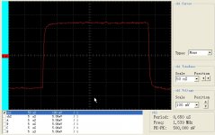
Please excuse me, since I am too lazy to put together my own things and start taking my own pictures just to show effects 🙂
I will use this link: CLICK
Take a look at Yamaha CDR HD1500, you will see rounded edges. Insufficient BW or poor high frequency performance will lead to rounded left edge of square digital signal.
Let's go further to Abraxalito's question...
Really, you think we are all idiots? You serve a "guru-like" phrase and the first links are from popularization magazines? Some of us have something more than google behind our skull.You guys need to do some research on the fundamentals before you waste anymore time speculating on the fine points or something I think most of you have never listened to, built, or measured and listened to different permutations ( logic families, bandwidth, digital cables, impedance matching, AC coupling) If you actually want learn something:
A Transport of Delight: CD Transport Jitter | Stereophile.com
The Jitter Game | Stereophile.com
Jitter & the Digital Interface | Stereophile.com
Rounded edges means nothing. Any decent receiver cares only about rising/falling fronts.Take a look at Yamaha CDR HD1500, you will see rounded edges. Insufficient BW or poor high frequency performance will lead to rounded left edge of square digital signal.
Last edited:
abraxalito said:Here's one I can't understand. Are you asking about what's the lowest and highest frequency we should pass over SPDIF?
HF performance is important, but also LF is important, which is often neglected.
Effect of poor LF performance can be seen here: CLICK.
Please take a look at Philips CDR560 or CD931. Right side of the square signal is tilted down. This is effect of poor LF performance. Things can be improved to some deegre with bigger coupling capacitor and while 1 uF C0G is very good (and difficult to find), this is often not enough, you will need more. 1nF teflon cap is only a joke from my side (see previous posts) 😀
And yes, you will need a cap, since small amount od DC will saturate tiny transformers core.
SoNic_real_one said:Rounded edges means nothing. Any decent receiver cares only about rising/falling fronts.
Go back and read "Is The AESEBU / SPDIF Digital Audio Interface Flawed ?" article again. If you low-pass S/PDIF, you will get rounded edges.
Rounded edges will have effect on rising/falling pattern. Start thinking in time domain 😀

Yes, receiver doesn't care if your edges are moving in time domain 🙂
Last edited:
You can always look at that Wall of Shame. They are crap, all of them.
Even cheap Mede8er streamer can be tweaked to run circles around them.
 .
.
Tweaked by my friend, following my advices.
I don't care for others, but in my world I would use low-leakage-inductance-high-interwinding-capacitance transformers, use attenuators when needed/possible and trying to terminate line with resistance, not inductance.
But YMMV.
Even cheap Mede8er streamer can be tweaked to run circles around them.
Tweaked by my friend, following my advices.
I don't care for others, but in my world I would use low-leakage-inductance-high-interwinding-capacitance transformers, use attenuators when needed/possible and trying to terminate line with resistance, not inductance.
But YMMV.
Attachments
Last edited:
Since many people listen to such equipment with evident satisfaction, doesn't that kind of imply that performance in this area is critical only to those who look a SPDIF signals with a 'scope?They are crap, all of them.
- Status
- Not open for further replies.
- Home
- Source & Line
- Digital Source
- Jitter? Non Issue or have we just given in?