Hello Folks!!
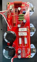
Has anyone built the JIMS AUDIO Version of the PASS ZEN 4?
I bought all the stuff unfinished from someone else than Jim’s Audio and I didn’t get schematics, or any other adjustment instructions, since it’s different from the original ZEN 4 I’m not sure how to adjust bias or quiescent current, etc.
Any suggestions?
I didn’t post this in Pass Lab Forum since it’s not the original design...
Thanks!!
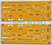
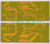


The person you bought the boards off should have received the schematic, parts list and adjustment procedure by email after they bought the boards from Jim's Audio, did you ask them?
You can also send Jim's Audio an email asking for the info.
You can also send Jim's Audio an email asking for the info.
Zen was a series of papers, not commercial amps so it should be fine posting this in the PL forum. The board looks like a Zen V4 using IRF9610 instead of ZVP3310. Adjusting bias is described in the paper as well
Zen Variations 4
Zen Variations 4
Adjusting bias is described in the paper as well
I’m familiar with the article from Pass Diy but its not only the IRF9610 what is different from the original design, that’s why I’m not sure if the same adjustment will work on this one, do you think it would?
What differences are you referring to? Parts or the layout?
I didn't look closely at the layout and yes it's not the same as the one in the paper but the components look like a match. Will it work? One easy way to find out 😉
The parts (other than the IRF044) are easily found and you can build with alternatives so no harm in trying is there? Many diy'ers made their own layouts and protoboards so as long as the schematic is correct it should be fine.
Bias procedure should be the same - I notice the pdf calls for 25K for R4 and the board shows that as 20K. I would go with 25K if you wanted to stay closer to the paper but the goal is to start with max resistance at R4 and slowly adjust so that you get 22V at the drain of Q1. The paper contradicts itself here saying 1/2 of regulated rail voltage + 2V, which it states as 42V, which should be 21+2 = 23V but the diagram shows 22V. I don't know how critical it is to get this exact but you could put it on a scope and just adjust for symmetrical clipping. That's what I would do but I have to warn you that I'm not exactly the smartest guy around here by far!!! 

Seems reasonable to me.
The only thing I would add is to not rely on clockwise/counterclockwise for
setting the pot.
The only thing I would add is to not rely on clockwise/counterclockwise for
setting the pot.
The person you bought the boards off should have received the schematic, parts list and adjustment procedure by email after they bought the boards from Jim's Audio, did you ask them?
You can also send Jim's Audio an email asking for the info.
Yeah, they’re really crappy people, they won’t share that information even when everything they sell is someone else’s design...
Last edited:
Ok, so I followed the adjustment procedure and all seemed to be good, after adjustment I left both channels running for about 1 hour and it got rather hot, heath sinks were about 63 degrees celsius even and drain voltage on Q1 with reference to ground was 22V, I left it at that last night.
Today I connected it to the scope and I don’t like what I see, with a 1kHz sine wave and an 8 ohm load I only get about 5Vpp before the wave deforms on the negative cycle only, there’s also a blip on the positive side, what can be wrong?
Please see the pictures below:
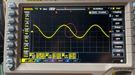
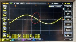
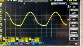
Today I connected it to the scope and I don’t like what I see, with a 1kHz sine wave and an 8 ohm load I only get about 5Vpp before the wave deforms on the negative cycle only, there’s also a blip on the positive side, what can be wrong?
Please see the pictures below:


- Home
- Amplifiers
- Solid State
- Jim’s Audio ZEN 4 Variation
