I've got one of these Boozehound phono stages...
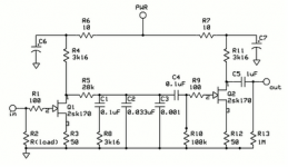
Boozhound Laboratories: JFET Phono Preamp Kit
Sounded real good till I decided to chnge the output caps to something nicer. Must have done something very wrong (perhaps hooked up the +/- on the power supply backwards) and now there's no sound. Nothing. Nada. Put the old caps back in. No sound. DC offset is OK. It's powered up now correctly +/-. Power caps are not open or shorted.
Did I cook the Jfets? Damn. Help.
Attachments
I've got one of these Boozehound phono stages...
Boozhound Laboratories: JFET Phono Preamp Kit
Sounded real good till I decided to chnge the output caps to something nicer. Must have done something very wrong (perhaps hooked up the +/- on the power supply backwards) and now there's no sound. Nothing. Nada. Put the old caps back in. No sound. DC offset is OK. It's powered up now correctly +/-. Power caps are not open or shorted.
Did I cook the Jfets? Damn. Help.
Any number of things may have happened. Do you have access to an oscilloscope? Meanwhile, the easiest thing to do would be to visually inspect the PCB for burned or discolored looking components, solder bridges, and cold solder joints or loose connections . Basically, carefully examine for anything which looks suspicious to the naked eye.
Last edited:
Hi ...
If you don't have access to an oscilloscope then maybe you have access to a digital multimeter? This could help test the DC voltages in the circuit as well as showing if/where there's signal if you put your finger on the input pin ... normally the finger - or body picks up hum and this can be used to test where there's no more signal.
Just in case you haven't done this then I'd personally wait connecting the cartridge to the circuitry until you're sure it works again ;-)
Greetings,
Jesper
I visually inspected everything. Nothing is burned on visually wrong. There is no continuity between the RCA positive in and RCA positive out either powered up or off...That's a bad sign, right?
Cartridge is OK, I tested w/another phono amp.
Power supply is 22V.
The jfets measure:
D-G : .32V
G-S : .45V
D-S : .13
Same on all Jfets.
I suspect the Jfets, I would imagine the resistors can take all sorts of punishment/backward voltages, the electro caps are not shorted or open and the other caps are all PIO/high voltage.
What do you think guys?
Hi again,
Yes, I would consider the Jfets as well since they basically are the only active components and if nothing looks burned then the resistors should be ok. And I reckon the electrolytics are ok since they hold the voltage (that is the PSU delivers and maintains 22 volts).
If it were me I'd just measure the voltage across R3 and R12 just to see if there's a lot of current running through the JFETs. The voltages across the JFETs are really low and my guess would be that:
- either they are burned ("shorted") and thus there would be a rather stable voltage across R3.
- or probably unlikely there's an extensive oscillation that makes DC measurements with a multimeter unreliable. But most often there's some sound effect associated with this like hum or just a bit of sound coming through the circuitry.
But my guess would be burned JFETs - although I hasten to add that I'm a JFET novice myself.
If you find out that the JFETs are burned due to reversed PSU voltages I would consider measuring the leakage current of the electrolytics as well to see how they fare (can be done with a resistor in series with the + terminal of the electrolytic and then the - terminal connected to ground. You need to unsolder it first, though).
BTW it looks like a circuitry that I could have taken interest in myself ;-) With good components and an utterly quiet powersupply I guess it could sound very good.
Regards,
Jesper
P.S.: Since the two stages of the circuitry is identical you can change one 2SK170 and if that changes the voltages - and lets sound through that stage - then there's a good chance that the other JFETs are also burned.
Regards, Jesper
Regards, Jesper
Thanks for the help guys. I guess I gotta decide to get some new Jfets (matched 2sk170BL's are not cheap these days...wow.) or build another phono amp. replaceing the jfets is gonna be no fun at all.
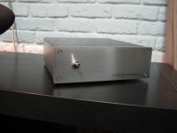
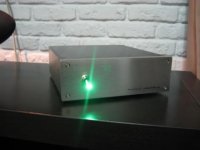
BTW, I highly recommend this Boozehound preamp. It's quite nice. Might try to salvage it if I can find more Jfets.
BTW, I highly recommend this Boozehound preamp. It's quite nice. Might try to salvage it if I can find more Jfets.
This thread may also give a means of obtaining matched FETs - see e.g. pages 5 & 6 (tony399).
Best of luck with your endeavors,
Jesper
Best of luck with your endeavors,
Jesper
matched 2sk170BL's | eBayThanks for the help guys. I guess I gotta decide to get some new Jfets (matched 2sk170BL's are not cheap these days...wow.) or build another phono amp. replaceing the jfets is gonna be no fun at all.
BTW, I highly recommend this Boozehound preamp. It's quite nice. Might try to salvage it if I can find more Jfets.
5.99 USD ,i think it is rather cheap. I did some changes on my board too and left channel was dead, testing,testing and testing could not find any problem. But someone told me to solder again, and i had done a cold solder 😱 my first one i never belived i could do that after so many years of soldering. Just check incase it is so simple. 🙂 It is a fantastic RIIA.

I have the same problem on mine. I did not change any parts. It get's power. 23.4v. I did discover one of the wires had snapped so I resoldered it. I will try to measure everything according to this thread and see what happens. I have soe spare time tomorrow 🙂
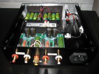
Turns out I had reversed the + and - power inputs. The board is not labelled well here...make sure your neg voltage is ground. This damaged the electrolytic caps. Replaced those and all was well. Still using it now.
Turns out I had reversed the + and - power inputs. The board is not labelled well here...make sure your neg voltage is ground. This damaged the electrolytic caps. Replaced those and all was well. Still using it now.
I have only powered it from an ac/dc wallwart.
Doesnt matter. Still puts dc to the board. Check to make sure neg from the wallwart is ground on the board.
IIRC, the pad that says 'PWR' next to it on the top of the board is actually connected to the ground plane (should be your negative connection). Kinda the reverse of what one might assume when wiring it up.
Doesnt matter. Still puts dc to the board. Check to make sure neg from the wallwart is ground on the board.
My dc inlet doesnt have any markings on it. I thought dc didnt have any polarity. Weird also, that it worked for so long before giving in..
Ummm...DC has polarity. Did you change anything with how the power supply is hooked up to the board right before you had this issue?
You have 2 power in holes on the PCB. Find the one that shows continuity with the one labelled "ground" or the negative lead of one of the caps. This is your negative pcb connection. The other is positive. Now take your meter and hook the red lead to the positive pcb connection and the black to the neg. pcb connection (you can use the solder pad if there is no bare wire).
Do you get negative or positive voltage? If it's negative then you are hooked up to the PCB backwards and your electrolytics caps are fried. If it's positive you are OK.
- Status
- Not open for further replies.
- Home
- Source & Line
- Analogue Source
- JFET phono stage (Boozehound) help!