I have a new JFET/MOSFET complementary-differential preamplifier, please visit
PRE complementary-differential preamplifier
and see the attached images.
PRE complementary-differential preamplifier
and see the attached images.
Attachments
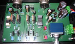
Yes simple and elegant (and good sounding), and important to mention IMHO: It´s actually a John Curl design.
R1 and R2 values have to be selected according to Idss of the matched JFETs. But the task is not very difficult, and digital multimeter is enough to make it.
Hi chlorofille,
yes, it sounds a bit different, and I would guess that listener's taste would judge.
Regards,
yes, it sounds a bit different, and I would guess that listener's taste would judge.
Regards,
Hi PMA
I expected a small Power amp based on this topology as we see many pre amps are around. Probably you would be the one to come with some DIY design ?
thanks for bringing out JC' s ideas
Kannan
I expected a small Power amp based on this topology as we see many pre amps are around. Probably you would be the one to come with some DIY design ?
thanks for bringing out JC' s ideas
Kannan
From the photographed pcb on your website I concluded that the cap multipliers are shared or am I mistaken ? Would it not be better to have separate ones for each channel ?
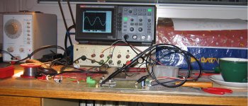
This is a setup to match JFETs 🙂
Attachments

Last edited:
PMA
I think your pre amp looks great.
Interestingly I just built a pre amp that is similar ( based generally upon the borbelly line amp ) using J fets in a symmetrical differential at the input and with 2 mosfets at the output connected to the input in a similar way to the one you have choosen.
My measurement equipment will a lot more basic than yours but I seem to get lower overall distortion when I cascode the front end jfets.
I had not adjusted R1 or R2 but I have been adjusting Re. Have you found that adjusting R1/R2 instead of Re gves lower distortion?
picture in 1st post shows 2sk389/2sj109.
more info on his website.
mlloyd1
more info on his website.
mlloyd1
Do you use monolithic JFET or matching by hand?
Have you found that adjusting R1/R2 instead of Re gves lower distortion?
Hi AMV8,
yes, because the key is to keep input JFETs in the most linear portion of the transfer characteristic, and R1/R2 serve only to set appropriate Vgs bias of the output MOSFETs. For more info, please visit
Distortion in JFET input stage circuits
Regards,
Do you use monolithic JFET or matching by hand?
Both. The 2SK389/2SJ109 are very difficult to purchase, in fact almost impossible. For this reason, there is a PCB design for 2SK170/2SJ74, and the devices are hand-matched.
Regards,
Both. The 2SK389/2SJ109 are very difficult to purchase, in fact almost impossible.
Why do not you, constructs from inaccessible parts?
- Status
- Not open for further replies.
- Home
- Source & Line
- Analog Line Level
- JFET/MOSFET complementary-differential preamplifier