Fair question al2002. The MC pre output Z is very low compared to a cartridge so the current noise penalty you get with a MM cart is essentially removed when you place the MC pre in front of the MM stage. Very often (from what I’ve seen anyway) the problem with signal chains is like this is the MC preamp is suboptimal wrt noise.
In a dedicated MC only preamp, you may be able to eek out a dB or more - the fundamental physics of thermal noise however place clear limits on how far you can go.
Edit: Ahh we cross posted Hans!
In a dedicated MC only preamp, you may be able to eek out a dB or more - the fundamental physics of thermal noise however place clear limits on how far you can go.
Edit: Ahh we cross posted Hans!
Last edited:
Note re my comment above, with FET input MM stages, the noise current penalty you have in bipolar input stages is not there since the current noise is usually about 2 orders or more lower in magnitude.
Notwithstanding input stage noise the quality of the power supplies can be more critical in JFET based devices than their bipolar counterparts. In the comparison at high frequencies of a JFET input device like the OPA1641 vs. a bipolar input AD797 the power supply rejection ratios (+/- PSRR) is 20dB for the OPA1641 and 40dB for the AD797 at 1MHz.
This is to suggest that the quality of the power supplies can be more critical in general in a JFET input device, seemingly the result of lower input stage gain. If it is considered that the noise generated in the power supply is the same for both, and the input signal the same for some MM cartridge the amplitude of signal magnified is lower for the JFET device being mirrored from the power supply into the second stage. This becomes another signal/noise issue that may dominate the outcome.
This is to suggest that the quality of the power supplies can be more critical in general in a JFET input device, seemingly the result of lower input stage gain. If it is considered that the noise generated in the power supply is the same for both, and the input signal the same for some MM cartridge the amplitude of signal magnified is lower for the JFET device being mirrored from the power supply into the second stage. This becomes another signal/noise issue that may dominate the outcome.
How do they compare in terms of PSRR at audio frequencies? Either way you are right that PSU quality is very important for phono circuits, you want very low noise and low output impedance over a wide frequency range, no matter what topology or devices in the actual amplification circuit. After all the amplifier only modulates the current from the PSU.
Ok here is a question for those well versed. A friend pointed out that most people can do a 24/96 recording of residual noise of their phono stage with the cartridge connected and arm in the air. Armed with around 10 seconds of noise recording, cart output and phono stage gain is there anything useful that could be calculated from that in terms of OOM performance?
Here are the noise measurements at different resolution settings. The Left channell is open circuit, the right channel has a 47 Ohm SMD TF soldered across the input to ground. Resolution is bin width in Hz L & R readings in uV RMS on QA401
Resolution/L/R
.732/10.52/15.84
1.46/11.5/17.36
2.92/12/18
5.8511.5/19.5
23.4/20/33
You will note there are quite large discrepancies in the noise voltages read from day to day, since I was getting 27-30 uV RMS over the last two days.
It seems at the higher resolutions, the readings are consistent between resolutions.
Hi Bonsai, I have repeated the check above with the following: 30 dB amp from QA470 (input shorted) into QA401, with 30 dB of gain entered into QA401 gain settings (so these are input referred). The QA470 uses a single OPA1612 to give 30 dB of gain.
5 averages, RMS 20 to 20K, no weighting:
2K FFT (23.4 Hz bin size): 520 nV, +/- 25 nV
4K FFT (11.7 Hz bin size); 505 nV, +/- 7 nV
8K FFT (5.85 Hz bin size): 508 nV, +/- 5 nV
16K FFT (2.92 Hz bin size): 506 nV, +/- 3nV
128K FFT (0.36 Hz bin size): 507 nV+/- 1 nV
Roughly, this is the equivalent noise of an 800 ohm resistor (20 kHz)
I think it's reasonable to say that you want a bin size that is smaller than your lower frequency of interest (eg 20 Hz RMS start frequency works well with 8K FFT which has 5.85 Hz of resolution).
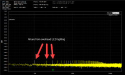
The spectrum for the last is attached. Note that something at 100 Hz is being picked up and runs across the spectrum. Could be mouse, could be the nearby JTAG probe. At the 30 dB of gain (and your even higher 80 dB of gain) you need to be as careful as you can that you aren't picking stray radiators up. In the end, turning off the overhead LED lights completely eliminated the 100 Hz.
But I'm pretty certain this config would show rock-solid RMS noise readings day in and day out, as would the standalone QA401. If you are seeing big daily jumps I'd look at environmental.
Attachments
USB battery pack + silent switcher, job done with galvanic isolation to boot.
This is unnecessary. AC mains PSU with regulated output is enough and will not add detectable noise. Phono pre may have additional filtering on board. DIY world is crazy. Most mistakes are made in wiring, grounding and shielding schemes.
Of course it is unncessary*. But in terms of time and cost saving for those of us without all the parts to hand it's not THAT daft. I agree on the wiring, grounding and shielding in DIY land.
* A hobby by definition is unnecessary
* A hobby by definition is unnecessary
Hi Bonsai, I have repeated the check above with the following: 30 dB amp from QA470 (input shorted) into QA401, with 30 dB of gain entered into QA401 gain settings (so these are input referred). The QA470 uses a single OPA1612 to give 30 dB of gain.
5 averages, RMS 20 to 20K, no weighting:
2K FFT (23.4 Hz bin size): 520 nV, +/- 25 nV
4K FFT (11.7 Hz bin size); 505 nV, +/- 7 nV
8K FFT (5.85 Hz bin size): 508 nV, +/- 5 nV
16K FFT (2.92 Hz bin size): 506 nV, +/- 3nV
128K FFT (0.36 Hz bin size): 507 nV+/- 1 nV
Roughly, this is the equivalent noise of an 800 ohm resistor (20 kHz)
I think it's reasonable to say that you want a bin size that is smaller than your lower frequency of interest (eg 20 Hz RMS start frequency works well with 8K FFT which has 5.85 Hz of resolution).
The spectrum for the last is attached. Note that something at 100 Hz is being picked up and runs across the spectrum. Could be mouse, could be the nearby JTAG probe. At the 30 dB of gain (and your even higher 80 dB of gain) you need to be as careful as you can that you aren't picking stray radiators up. In the end, turning off the overhead LED lights completely eliminated the 100 Hz.
But I'm pretty certain this config would show rock-solid RMS noise readings day in and day out, as would the standalone QA401. If you are seeing big daily jumps I'd look at environmental.
Matt, thanks for your feedback. I am circling back to look at this sometime later this week - busy with other stuff at the minute.
(Just to reiterate, I remain extremely happy with the QA401 and the support you provide)
Of course it is unncessary*. But in terms of time and cost saving for those of us without all the parts to hand it's not THAT daft. I agree on the wiring, grounding and shielding in DIY land.
* A hobby by definition is unnecessary
Bill, you are right. When looking at the spectra in the first posting of this thread, you will see 50Hz and 150Hz mains components.
Much too small to worry about, but yet detectable.
Hans
Are you sure they originated from the power supply and not from turntable lever or cartridge shielding. I would not be at least self-assured about the PSU as a main source of those small mains lines. Based on experience and many measurements done on real systems, not on phono preamps in isolation.
There is certainly a limit on how low mains pickup can be lowered. Hans does appear to have some of the lowest radiated fields in Europe at his house, but if I remember correctly he could pick up low frequency traffic noise!
This is unnecessary. AC mains PSU with regulated output is enough and will not add detectable noise. Phono pre may have additional filtering on board. DIY world is crazy. Most mistakes are made in wiring, grounding and shielding schemes.
No argument on either count. 🙂
Are you sure they originated from the power supply and not from turntable lever or cartridge shielding. I would not be at least self-assured about the PSU as a main source of those small mains lines. Based on experience and many measurements done on real systems, not on phono preamps in isolation.
In one of the two images the input was shortened according to the text, so no TT related mains pick up, but 50Hz and 150Hz components were the same in both images.
But as I mentioned, detectable but totally harmless.
Hans
This is unnecessary. AC mains PSU with regulated output is enough and will not add detectable noise. Phono pre may have additional filtering on board. DIY world is crazy. Most mistakes are made in wiring, grounding and shielding schemes.
Agreed. Though being contributors/ readers/ experimenters in DIY we may all be a little crazy... if not a whole lot. It is believed that many circuits cannot be reasonably implemented by DIYer's without more extensive knowledge of wiring, grounding and shielding being better understood. Grounding and shielding may be more of black magic to most, since there are many textbooks on this subject.
This brings up a point that isn't clear. This has to do with the manner of wiring from a cartridge to a preamp. Typically each coil is connected to coaxial cable with one end to the centre conductor and one to the "shield". A separate ground lead then that attaches the metallic surfaces of the turntable to the chassis of the preamp.
To whatever extent this can be successful it was found that a ferrite bead or core greatly improved the sonic performance under some circumstances. This suggests that conventional phono leads do not shield from RF very well, seemingly that the ground "shield" (as an active return current conductor) is adding signal to the input shielded conductor. This raises the question of containing both current carrying conductors within a shield as opposed to using some separate ground wire that works for audio frequency signals. Basically it seems that wiring ought to be done via XLR's to inhibit such RF interference from cutting through either of the coil leads... being instead connected in some internal twisted pair configuration.
Ultimately is the advantage of using FET's to restrict RF interference the result of historically inadequate or antiquated RF shielding? Note that this is not to suggest
the necessity of using differential inputs, rather that the coils are floating whereupon one end of each coil can then be connected to a reference point on the input preamplifier. Am I missing something?
There is certainly a limit on how low mains pickup can be lowered. Hans does appear to have some of the lowest radiated fields in Europe at his house, but if I remember correctly he could pick up low frequency traffic noise!
Hi Bill,
Probably all rural areas with mains cables burried in the ground and windturbines tens of miles away must have significantly less field radiation as large cities, so I can’t imagine that my place is an exception, but yes I’m quite happy where I live.
Your memory serves you well, the fixed 120Hz that my TT picks up during the day must be caused by some ground resonance from a highway a few miles away, I can’t think of any other reason in a 50Hz country.
After 20:00 it stops and so does the trafic, a real mystery. 😀 😀 😀
Hans
- Home
- Source & Line
- Analogue Source
- JFET input phono preamp for MM