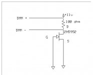
Is this the correct method? I followed Nelson Pass's description, or at least I'm hoping I did. ( "I connect the Source and Gate to ground (for N) and measure the current.
With an 11 volt supply and assuming a typical value of 10 mA, use 100 ohms
in series with the Drain (the voltage drop across it will give you the Idss) for
a Vds of about 10V, and connect the other side of the resistor to +11V.
Reverse the supply polarity for P channel." )
With an 11 volt supply and assuming a typical value of 10 mA, use 100 ohms
in series with the Drain (the voltage drop across it will give you the Idss) for
a Vds of about 10V, and connect the other side of the resistor to +11V.
Reverse the supply polarity for P channel." )
Attachments
Watch the power dissipation.
BAD is when they are too hot to touch.
Otherwise, yes this will work fine.
BAD is when they are too hot to touch.
Otherwise, yes this will work fine.
Just to follow up, this is the first time I have matched Jfet's. Out of twenty fets, here's the results in mA's:
2 x 5.00
2 x 6.16
2 x 4.82
then:
6.59
6.37
5.85
5.86
5.71
6.19
6.44
6.07
6.11
5.09
4.86
4.13
4.92
4.40
Is this pretty typical? The Jfet is a 2N5952. I needed four matched pairs.
2 x 5.00
2 x 6.16
2 x 4.82
then:
6.59
6.37
5.85
5.86
5.71
6.19
6.44
6.07
6.11
5.09
4.86
4.13
4.92
4.40
Is this pretty typical? The Jfet is a 2N5952. I needed four matched pairs.
Your load resistor is the wrong value. Should read 1k for 10mA otherwise 100R will draw 100mA.
POP!
POP!
Actually the transistor will draw Idss, but the majority of the supply voltage will be Vds. 6.59mA X 100R= 0.659V. 10.341V X 6.59mA= 68.2mW. Should be OK for even a SOT-23 J-fet. A higher goss J-fet like J111 or 2N4091 might begin to get warm. It is best to try to have relatively the same Vds for each DUT so you don't want it too large, but large enough to get an accurate measurement. 100R is fine here. 😎
The self bias with or without a source resistor is why J-fets make such great current sources, especially when cascoded. 😉
The self bias with or without a source resistor is why J-fets make such great current sources, especially when cascoded. 😉
One last question, what is a reasonable difference for considering being matched? For instance, is 6.11, 6.16 and 6.19 close enough?
That 1% low and 1.5% approx high . Given 1% resistors I say that a good match.One last question, what is a reasonable difference for considering being matched? For instance, is 6.11, 6.16 and 6.19 close enough?
Hello Ripcord
Can you help me out. I'm building a pre-amp and using the 2N5952. The problem I have is the datasheet does not show pin-out. Can you tell me what the pin-out is?
thanks
Can you help me out. I'm building a pre-amp and using the 2N5952. The problem I have is the datasheet does not show pin-out. Can you tell me what the pin-out is?
thanks
Does anyone know if simply using a 9V battery connected to the drain while shorting the gate/source to GND and measuring the current with an ammeter is considered a satisfactory method of determining Idss and matching JFETs? I'm working with K170 and J74.
From what I understand the drain resistor isn't really necessary since JFETs self bias (unless you are using a voltmeter rather than an ammeter.)
From what I understand the drain resistor isn't really necessary since JFETs self bias (unless you are using a voltmeter rather than an ammeter.)
Does anyone know if simply using a 9V battery connected to the drain while shorting
the gate/source to GND and measuring the current with an ammeter is considered a
satisfactory method of determining Idss and matching JFETs?
That's right, 9V is enough. The resistor is just used to measure the current,
if you don't have an accurate ammeter.
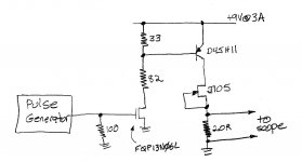
Use pulse techniques to measure IDSS of the Nchannel JFET whose part number is "J105" (datasheet). Even though this device is in a plastic TO-92 package, its datasheet minimum IDSS is 500 mA (!!) If you measure that at VDS=5V, the power dissipation will be a minimum of 2.5 watts, FAR greater than the absolute maximum rating (0.62 watts).
Thus: make measurements with low duty-cycle pulses. The datasheet says "duty cycle < 2%", I recommend duty cycle < 0.5%. Now the average power dissipation during testing is a couple dozen milliwatts, which keeps self-heating manageably small.
_
Thus: make measurements with low duty-cycle pulses. The datasheet says "duty cycle < 2%", I recommend duty cycle < 0.5%. Now the average power dissipation during testing is a couple dozen milliwatts, which keeps self-heating manageably small.
_
Attachments
Last edited:
Hi Mark,
Any reason not to use a BJT instead of the FQP13N06L Mosfet? Most members would probably have a suitable transistor on hand. A mosfet might actually do odd things due to the gate charge if the pulse generator doesn't have a high current capacity.
Just a thought.
-Chris
Any reason not to use a BJT instead of the FQP13N06L Mosfet? Most members would probably have a suitable transistor on hand. A mosfet might actually do odd things due to the gate charge if the pulse generator doesn't have a high current capacity.
Just a thought.
-Chris
Sure, an NPN BJT would work in the first stage. Just verify that its SOA includes 9V @ 100mA and make sure your base resistor(s) are small enough and your pulse generator is macho enough, to deliver a full ten mA of NPN base current. You want (Ic/Ib) = 10 to get good VCEsat. D44H11 would be the natural choice since it's the NPN complement of the D45H11 PNP that's already in use. I recommend avoiding an integrated Darlington because they switch very slowly.
Hi Mark,
Sure thing. It's great to give people a choice. Some Darlington transistors are faster these days since they include the speed-up resistors to help turn the outer transistor off faster.
Hi CBS240,
-Chris
Sure thing. It's great to give people a choice. Some Darlington transistors are faster these days since they include the speed-up resistors to help turn the outer transistor off faster.
Hi CBS240,
Yes, they do. Remember seeing them in early car power amplifiers and some small domestic amplifiers? They were popular for a while.those D44 and D45 transistors make excellent output devices, ~20W class AB.
-Chris
Your load resistor is the wrong value. Should read 1k for 10mA otherwise 100R will draw 100mA.
POP!
The 100r passing a typical 10mA of Idss will have a Vdrop of 1V................. 100R is fine here. ........
That leaves 10V of the available 11V supply to drop across the jFET.
Most jFETs are specified for Idss @ 10Vds.
Ripcord got it exactly right for a 10mA Idss.
If Idss is lower one just dials the 11V output of the lab supply a little bit lower.
If Idss is higher then the applied Vds drops and helps to not overheat the jFET.
Don't try to measure high value Idss using constant current testing/measurement.
I found that going to 20mA Idss was already in trouble, the Tj rises too fast to get any sensible measurement data for comparing to other devices.
- Status
- Not open for further replies.
- Home
- Amplifiers
- Solid State
- Jfet Idss Tester