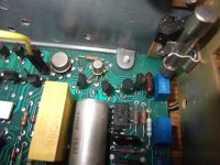
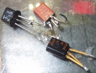
I have found a short circuit FET in a late 1970s Fluke DMM.
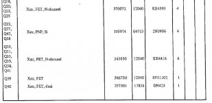
It is shown in the parts list as SF51102 and the part is marked U3146.
The other FETs are all shown as N-gate however this one has no comment by it in the parts list😡
I web search produces less information than what little is shown in the manual.
I think it is a P-gate as the driver transistor feeds the gate through a resistor from -18 volts with the gate resistor going to zero volts.
Has anyone got a data sheet for one of these?
Attachments
My guess is the the "SF" is a custom device for Fluke. Likely it is just a sort of someone's existing catalog product, perhaps with specified Idss range or Vgs(off) or whatever.
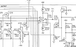
It is drawn a n channel and the gate is swinging between 0V and -2V2.
The load is clamped at around -0.6V, so I suspect a n-channel with very low Vgs OFF (<1.5V).
When the fet is ON, the gate is almost forward biased
The load is clamped at around -0.6V, so I suspect a n-channel with very low Vgs OFF (<1.5V).
When the fet is ON, the gate is almost forward biased
I will have a go at testing some of the JFETs I have got and see if I can find something that works as expected on a bench test rig.
Only 3 semiconductor manufacters made the U series fets, Intersil, Siliconix and Teledyne Semiconductors and none of their standard part numbers went as high as U3146.
It must be a custom part for Fluke, so you are going to either have to get the part from Fluke, or do what you are trying with substitution.
It is in series in your circuit with R75, the 30.9k resistor, so without seeing the whole circuit, I am assuming it is used as a switch to an integrator circuit. If that is the case, I might try the lowest ON resistance low leakage N-Fets you have, such as the (KE/PN/2N) 4391 or even 2N4091 so that it has the least effect (particularly with temperature changes) on the circuit.
It can't be that special being as it has a 1978 date code on it.
It looks like I could order a selection of modern JFETs next time I am after some good branded parts from one of the better local suppliers and try some in it if what I have already got does not work.
It looks like I could order a selection of modern JFETs next time I am after some good branded parts from one of the better local suppliers and try some in it if what I have already got does not work.
Nothing has happened in silicon jfet technology since the 1970s. This part does not need low Rds as it is series with 30k9. Anything better than 300R is already <1%.
The Vgs off is very unusual. There were Toshiba jfets with low Vgs, but mostly unobtainable now. General purpose devices need far too high voltage to turn off. I am not sure why the Vgs swing is deliberately so low, low charge injection perhaps?
The Vgs off is very unusual. There were Toshiba jfets with low Vgs, but mostly unobtainable now. General purpose devices need far too high voltage to turn off. I am not sure why the Vgs swing is deliberately so low, low charge injection perhaps?
I have had another look at the circuit.
There is a drive to Q36 controlling the sampling.
Q36 has a 6.2K emitter resistor that also carries the base currant.
I would estimate it to drop 6 volts.
There is then two 10K resistors forming a potential divider to ground with the gate of the FET at the junction of these. I would estimate these to drop 6 volts each as they don't carry base currant giving a gate drive of -6 volts.
Perhaps the Vgs is not that special after all.
I will have a look at the FETs I have got. I know that I have got some 2N3819s NOS and some 2SK something pulled from some Japanese kit in the 1980s. I have got some other transistors that I have never fully gone through that include some MOSFETs and there could well be some "J"s in there too.
I have had a dig into boxes and found some FETS.
There were 4 types for me to try. First the 2N3819 requires too much Vgs so it is out of the running.
The other three I have found are all pulls and all work at under 2.7 volts from a diode tester and the first try will be a 2SK19 as that begins to turn off at 0.5 volts from an ohms range while the other two just go off completely with the diode tester and stay fully on with the resistance range.
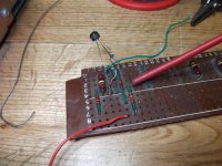
I did say in message 4 about a bench jig and yes indeed a crude one has indeed appeared.
I will put them in and see how they go tomorrow.
There were 4 types for me to try. First the 2N3819 requires too much Vgs so it is out of the running.
The other three I have found are all pulls and all work at under 2.7 volts from a diode tester and the first try will be a 2SK19 as that begins to turn off at 0.5 volts from an ohms range while the other two just go off completely with the diode tester and stay fully on with the resistance range.
I did say in message 4 about a bench jig and yes indeed a crude one has indeed appeared.
I will put them in and see how they go tomorrow.
Attachments
- Status
- Not open for further replies.
- Home
- Design & Build
- Parts
- JFET identity needed