It is a trade off: the transition can be made arbitrarily fast, but then it won't be clickless anymore.however I fear that the switching time will be a bit high (~1 s for full mute). During on-to-off or off-to-on transition the signal might be seriously distorted, which becomes audible at such long transition times. Can R5 be reduced to something like 100k without compromising on-performance?
With the original values, the total switching time was 200ms, with the transition lasting ~80ms.
Here is an example where the delay is shortened to 1.5ms, and the transition time to several µs.
This will cause an audible click, particularly if the audio signal has a high bass contents.
Attachments
I presume a meaningful transition time would be around 20 ms. What's 10 Hz distortion (on-state) under these conditions?
Samuel
Samuel
Sam
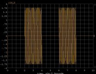
Sorry for my error with the dgs, at least the components were the right way round in the circuit and only wrong in my head! The muting action is better when I bias form a separate 20V supply with all of the positive peaks being clamped to 0V and only negative peaks of around 80mV. Here is the muted output waveform. The circuit is still set with the 3V J1 source voltage
It looks like maybe the J201 could be worth a try, not sure exactly what you mean with the -9V bias arrangement though!
Elvee, thank you and my sincere apologies!! I got so carried away with the distortion figures you quoted, that I did not notice your take on the switching circuit!
Well that looks as though it works quite well. The 20K resistor on the output of previous schematics is to model the input impedance of the mixer input. If your circuit has an 18K output resistor, would the combined 9.5K load down the buffer and lead to more distortion?
It looks like you guys are getting close!
Cheers
Ray
Sorry for my error with the dgs, at least the components were the right way round in the circuit and only wrong in my head! The muting action is better when I bias form a separate 20V supply with all of the positive peaks being clamped to 0V and only negative peaks of around 80mV. Here is the muted output waveform. The circuit is still set with the 3V J1 source voltage
An externally hosted image should be here but it was not working when we last tested it.
It looks like maybe the J201 could be worth a try, not sure exactly what you mean with the -9V bias arrangement though!
Elvee, thank you and my sincere apologies!! I got so carried away with the distortion figures you quoted, that I did not notice your take on the switching circuit!
Well that looks as though it works quite well. The 20K resistor on the output of previous schematics is to model the input impedance of the mixer input. If your circuit has an 18K output resistor, would the combined 9.5K load down the buffer and lead to more distortion?
It looks like you guys are getting close!
Cheers
Ray
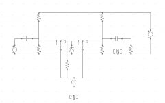
Sorry, I missed this thread since I had worked this out a while ago. Here the resistors are all 20k and the current source is just a simple npn bipolar on/off switch. With the npn off the FET gates tap the center point of the two channels, this is an old trick for making linear VCA's. With BF862 FETs the THD is <-110dB at 3.5 Vp-p and feedthrough is >-100dB.
The zener is really just a 1n4148, Vs is 9V for my plot.
The zener is really just a 1n4148, Vs is 9V for my plot.
Attachments
Last edited:
I put 18K in my sim to symbolize the two parallel resistors you used in your schematics.Well that looks as though it works quite well. The 20K resistor on the output of previous schematics is to model the input impedance of the mixer input. If your circuit has an 18K output resistor, would the combined 9.5K load down the buffer and lead to more distortion?
The value is unimportant, as long as there is a DC path to the GND; if you want to operate the circuit with an open output, you could default it to 1Meg.
If you lower it substantially, it will increase the voltage drop across the FET, hence the distortion too.
But you would need to go very low to come close to the distortion of the buffer stage: the distortion of the switch alone is 0.0012%
The following version switches in ~20ms. The distortion at 10Hz is unchanged.
You can play with the capacitor values to obtain the optimum trade off between speed of action and audibility.
Attachments
Thanks Elvee!
This looks great, the application will call for the output resistor as it is quite possible that the output could get disconnected in use. I originally thought 470K but a 1MEG component here reduces the distortion a tiny bit and therefore that's what I will go for as you suggested. I will try and breadboard this tonight and see how it sounds and road test the switching to see if it is quiet and effective. I will let you know as soon as I have some results.
What are your thoughts on the stability and reliability of the circuit as it will be used similar to an effect pedal, where it will be connected to mixer and then various sources will be plugged into the input, guitars, piezo pickups even CD players etc, as in an open mike session at a music club. It will also needs to be immune to unexpected muting or un-muting!?
Hi Scott!
Many thanks for your switching circuit it looks very interesting and quite high performance. I have only J201 & 2N5460 FETs to hand and therefore I will try out Sam and Elvees solutions first as they fit my needs of simplicity (it needs to be simple for me to understand it!!) and low component count. Unfortunately my knowledge hinders my understanding of how your solution works, but thanks to the help and time you folks have been given me here, I am learning!
Thanks all
Ray
I bread boarded Elvee’s take on the circuit and it muted a treat, with no clicks or pops whatsoever. I had to use a 330nF for time constant C4 instead of 470nF and therefore I increased R6 to 1.5K, not quite the same time delay but close enough. The muting is very smooth and quiet indeed and with more than enough attenuation for my intended application, so hats off to Elvee!!
I then started to think about the Pass B1 buffer that Andrew suggested, using another FET to put a CC in J1 source, and simulated the circuit below
This seems to work extremely well in simulation land with a decrease in THD of nearly 10x as well as allowing a larger input signal and lowering the circuit consumption to boot! I will try this circuit out tomorrow as I happen to have a couple of J201’s with practically identical Idss (565uA). My guess is they should make good candidates for the circuit. If this works, then it looks like the circuit is in the bag. Does anyone see any potential problems with the circuit above?
Cheers
Ray
I then started to think about the Pass B1 buffer that Andrew suggested, using another FET to put a CC in J1 source, and simulated the circuit below
An externally hosted image should be here but it was not working when we last tested it.
This seems to work extremely well in simulation land with a decrease in THD of nearly 10x as well as allowing a larger input signal and lowering the circuit consumption to boot! I will try this circuit out tomorrow as I happen to have a couple of J201’s with practically identical Idss (565uA). My guess is they should make good candidates for the circuit. If this works, then it looks like the circuit is in the bag. Does anyone see any potential problems with the circuit above?
Cheers
Ray
Thanks Elvee!
Hi Scott!
Many thanks for your switching circuit it looks very interesting and quite high performance. I have only J201 & 2N5460 FETs to hand and therefore I will try out Sam and Elvees solutions first as they fit my needs of simplicity (it needs to be simple for me to understand it!!) and low component count. Unfortunately my knowledge hinders my understanding of how your solution works, but thanks to the help and time you folks have been given me here, I am learning!
Thanks all
Ray
No problem, I didn't have time for a full description so I will post it separately later. BTW J201's would work just fine and the circuit can have a trim for Idss balance.
Thanks Scott! appreciate it!
To be honest Elvee's switching circuit above works perfectly and has the benefit of being delightfully simple so I will stick with this if I can. I am going to try the dual FET buffer with it tonight, if I get the time, and see how it all sounds and works.
As I seem to be getting near the finished circuit, do you guys think the back to back zener across the input on my original circuit are necessary? This was intended to offer some protection to the FETs against static or any high voltages on the input. You have to consider that this unit is a plug in device to interface many different types of audio devices to my mixer, and not a circuit that is left permanently connected to equipment. If you do not think they will add anything to the circuit, I will leave them off in the interest of input impedance and distortion.
Cheers
Ray
A pair of simple diodes to the supply rails will be as effective, and less intrusive than zeners.As I seem to be getting near the finished circuit, do you guys think the back to back zener across the input on my original circuit are necessary? This was intended to offer some protection to the FETs against static or any high voltages on the input. You have to consider that this unit is a plug in device to interface many different types of audio devices to my mixer, and not a circuit that is left permanently connected to equipment. If you do not think they will add anything to the circuit, I will leave them off in the interest of input impedance and distortion.
If you want your two-transistor buffer to match the switch's distortion, you can use the trick shown below: it will only eat up 0.6V headroom, and give an order of magnitude improvement over the plain vanilla version.
It is important however to have a spotlessly clean power supply to be able to use it!
Attachments
Do you think the back to back zener across the input on my original circuit are necessary?
Some sort of protection is surely advantageous, however the zeners are IMO not the best solution here. Zener diodes have very high nonlinear capacitances which will generate ample distortion with high source impedances (try it with 100k in series with V1).
I'd use two 1N4148 diodes connected to rail/ground, after the AC coupling capacitor. Also I'd add a bit of series resistance (100 Ohm) ahead of them for current limiting.
Samuel
Hi Sam/Elvee
Diodes across the supply to ground is the way I will go then. I was noticing that the Zeners effected the THD and although probably not to an extend that would ever be evident in my application, it puts rest to the paranoia that spice simulation gives you the luxury of!!
Elvee, you tease me!! this looks very interesting indeed, but why two outputs, can you give me a hint as to what is going on here and how it is used? The power will always just be a 9v battery and so power supply issues should be OK? The battery life is a concern though and as the simple 3 FET circuit only draws less than 600uA, this would seem to be ideal
My guess is that the additional component count/complexity in your latest circuit take, although very worthwhile on specifications, would probably not make a huge amount of difference to the circuits overall "sound", and that it will be used in front of audiences that would not know a good sound if it jumped up and bit them on the rear! However, I will know there is a difference and that could be just enough to swing it 😀
Cheers guys
Ray
...it will only eat up 0.6V headroom, and give an order of magnitude improvement ...
It's worth noticing that the JFET version of White Cathode Follower you drew has much lower output impedance (thanks to the modulation of the CCS) and is capable of driving much lower loads (1k with k170 or BF862) and longer cables...
I drew the two circuits to make the comparison good/better easier.Hi Sam/Elvee
Diodes across the supply to ground is the way I will go then. I was noticing that the Zeners effected the THD and although probably not to an extend that would ever be evident in my application, it puts rest to the paranoia that spice simulation gives you the luxury of!!
Elvee, you tease me!! this looks very interesting indeed, but why two outputs, can you give me a hint as to what is going on here and how it is used? The power will always just be a 9v battery and so power supply issues should be OK? The battery life is a concern though and as the simple 3 FET circuit only draws less than 600uA, this would seem to be ideal
My guess is that the additional component count/complexity in your latest circuit take, although very worthwhile on specifications, would probably not make a huge amount of difference to the circuits overall "sound", and that it will be used in front of audiences that would not know a good sound if it jumped up and bit them on the rear! However, I will know there is a difference and that could be just enough to swing it 😀
Cheers guys
Ray
You don't have to build both versions.
It's like the washing powder advertisements: some people think they have to tie theirs towels in knots before putting them in the washing machine.

DOH!!
Sorry Elvee, I promise I will try harder in future!!! 🙄
Well this looks absolutely spot on! I will bread board the lowest THD version of the two circuits with the switch on the output and let you know the results. I happen to have a couple of J201's with the same Idss and so should work well in the circuit.
Cheers all!!
Ray
I bread boarded Elvee’s circuit (post #30 , lowest THD variant) and it sounds absolutely fantastic! Very lively and transparent sound with both CD input as well as a tryout with an acoustic guitar (piezo) input. In fact I found myself playing the guitar through the buffer and into a headphone amp for quite some time longer than expected, as the sound was that good I wanted to try loads of tunes out! I had to use 4.7uF caps in place of the 1uF Elvee specified as I had no 1uF’s
The sound quality either side of the switch circuit was identical or at the very least totally inaudible and the switch function with 330n and 1.5K is smooth and silent. So it looks like the circuit is in the bag!
As long as you guys can see no problems with stability etc in using 4.7uF caps in place of the 1uF’s, then the next step is to build it and box it up. I am a very happy chap!!
Cheers
Ray
No problem, the larger the cap, the better. In fact, I threw 1µ without any calculation.As long as you guys can see no problems with stability etc in using 4.7uF caps in place of the 1uF’s, then the next step is to build it and box it up.
Remember that C2 and R5 symbolize the output cap plus the load (external), don't duplicate them in the complete circuit.
C3 could be made substantially smaller if R3 is increased accordingly. I didn't calculate the values either, you could adopt the same values as for the input, 47n and 2.7meg.
Hi All
Well I have my JFET buffer built and it sounds great and works a treat!! Thought I would post a pic as below. I would just like to thank all the people on the forum that helped me with this and I would especially like to thank Elvee and Samuel who's time and effort was priceless! I owe you guys a beer!!
Cheers
Ray 😀
Well I have my JFET buffer built and it sounds great and works a treat!! Thought I would post a pic as below. I would just like to thank all the people on the forum that helped me with this and I would especially like to thank Elvee and Samuel who's time and effort was priceless! I owe you guys a beer!!
An externally hosted image should be here but it was not working when we last tested it.
Cheers
Ray 😀
- Status
- Not open for further replies.
- Home
- Amplifiers
- Solid State
- JFET experts needed!