Hi all,
I’m working on a programmable tube preamp. Part of that is achieving some way of switching cathode capacitors with a microcontroller. Jumping past LDRs and Relays due to size I’m investigating the use of P channel JFETs as used in many Mesa and some Marshall amps.
The J175 (rds on max of 125 ohms) is the most common I can see in schematics, though I’ve found a Marshall DSL using J174. The “problem”, if you can call it that, is that the guaranteed Vgs off of these parts is 6v or higher. And a microcontroller is going to be toggling 0 to 5v natively. So they won’t be fully “off” but perhaps they get close enough?
I can use an NPN switch to interface but I have found the J176 which has a max Vgs off of 4v in exchange for a higher rds on of 250 ohms max. So I wired a couple up and collected some characteristic data which is attached. I appraised their switching capability as raw resistance and as a voltage divider since there will likely be a small positive voltage on the drain from leakage through the cap. And in the interest of seeing how good of a transistor switch is need I rechecked the V and R across the FET with a residual .5v on the gate to simulate a weak pull down.
I’m curious if others that have used JFETs this way can comment on their implementation choices, the role of part to part variability in deciding which of these options is best, and if thermal or voltage variation should be of concern. My gut says that as long as the FET gets above, say, 20k consistently that’s a good enough “off” and anything approaching 100 ohms is a good enough “on”.
Last edited:
I am in the early stages of designing a new guitar amp. One of the hardest parts is figuring out just what features you need, what you want, and what you don't want. I have gathered lots of random bits of information including the schematic of my old ADA MP-1. It uses a pair of j-fets to boost the gain on the input stages. The schematic has no part numbers and doesn't always match my unit, which is stuck in a rack at the moment. It was built in the late 80's, so those fets are extinct by now as is the case with most of the parts in the unit.
I have experimented with mosfets in this application in the past with poor results. An experiment with a 12AX7 and a bag full of j-fets is coming. I did figure out that the 100K resistor is needed in any switched cap circuit to avoid a large pop when the fet or relay closes. The idea is to keep the DC charge the same between the open and closed positions.
I have experimented with mosfets in this application in the past with poor results. An experiment with a 12AX7 and a bag full of j-fets is coming. I did figure out that the 100K resistor is needed in any switched cap circuit to avoid a large pop when the fet or relay closes. The idea is to keep the DC charge the same between the open and closed positions.
Attachments
Feature creep has had me stalling out for a long time. Trying to do this in a small enclosure and balancing scope with expandability/experimentations is tough.
My core project is a clone of the Mesa Triaxis. I think can get there. I’ve already done some breadboarding of their LDR control scheme and I have a working 5 band EQ that can be adjusted over SPI. I’m making final decisions on features and halfway through board layout… ok maybe less than half.
Can you comment on what you didn’t like about mosfets? I just bought some BS170 on a recommendation from a GroupDIY.com member.
In reality I didn't spend enough time tinkering with it to see if I had been making a Dumm Blonde mistake or not. I got the idea while testing out ideas for the Hundred Buck Amp Challenge which started back in 2011 during a time when I was working 70+ hours a week as an EE at Motorola. I created three unique amp designs for that thread. One never worked right, the second was an absolute lowest possible cost design (under $50) to prove a point, and the third was a "what could I make for $99.99."
My EE career ended in 2014, and I packed up and left South Florida. The remains of all three amps were tossed in a box along with lots of other stuff. Once our house was built and I had a place to tinker, the box was opened. The ultra low buck 4 tube amp that made about 2 watts still worked, but sounded rather mundane. Since the HBAC had run its course and there were no more rules, I tinkered with it for a while and turned it into something that I still use.
There were two versions of the $99 amp differing only in the choice of tubes. Both used a series heater string so that a cheap isolation transformer could be used for the power transformer. Both used an Antek power toroid as the OPT. These were replaced with real guitar amp OPT's once the contest was over. The version with 9 pin output tubes still works and is sitting on top of the speaker cabinet. Now if I can only figure out how to fit that REAL reverb tank into the amp......
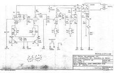
That amp had the "mosfets in the cathode circuit" experiment in it. The amp also had WAY too much gain and was highly microphonic. The schematic is included. The tubes were 26AQ8/UCC85 which had a Mu of 50 compared to 100 for the usual 12AX7, so I added an extra gain stage. I remember experimenting with a variable power supply on the line that feeds the gates of all the mosfets and finding very little change in gain. Unfortunately, my work schedule and the contest deadline left this unresolved. I ripped out the mosfets, replaced them with resistors or trimpots, cut a few traces and ran jumper wires to bypass one gain stage. This created a playable amp that still works.
I also hacked up the octal version to run 6 volt tubes, and stuck in some 6BQ7's and EL34's. It made for a very loud amp with way too much gain. Note the fancy "tube damper" on the input stage. I tried several different tube combinations, but all were microphonic or unstable. It hasn't been touched since I left Florida.
I have breadboarded up a single tube gain stage which will see some serious experimentation soon. It can be used with a wide variety of tubes, both triodes and pentodes. I will likely revisit the mosfets, J-fets, vactrols, and even digital pots for cathode, screen grid, and plate load tweakability. The original mosfets in the cathode circuit was tried in a multi stage design where there were other issues, and too many variables. Single stage experiments allow for more controlled testing.
The end goal is for a new guitar amp with a large and "creeping" feature set with total recall of all settings. I like the MP-1 concept, but my 35+ year old MP-1 has become quite intermittent and microphonic to be of much use now. Its antiquated microprocessor setup is well old unreliable and large.....I'll likely use a Teensy 4.1. I grew up in the Miami area listening to 60's surf music on the radio and playing it on my guitar. Got to have reverb for that surf music sound, so my amp will have a standard sized (17 inch) reverb tank, so it will be at least 20 inches wide. That Stratocaster sized tank will be in a bigger plug in cabinet.
My EE career ended in 2014, and I packed up and left South Florida. The remains of all three amps were tossed in a box along with lots of other stuff. Once our house was built and I had a place to tinker, the box was opened. The ultra low buck 4 tube amp that made about 2 watts still worked, but sounded rather mundane. Since the HBAC had run its course and there were no more rules, I tinkered with it for a while and turned it into something that I still use.
There were two versions of the $99 amp differing only in the choice of tubes. Both used a series heater string so that a cheap isolation transformer could be used for the power transformer. Both used an Antek power toroid as the OPT. These were replaced with real guitar amp OPT's once the contest was over. The version with 9 pin output tubes still works and is sitting on top of the speaker cabinet. Now if I can only figure out how to fit that REAL reverb tank into the amp......
That amp had the "mosfets in the cathode circuit" experiment in it. The amp also had WAY too much gain and was highly microphonic. The schematic is included. The tubes were 26AQ8/UCC85 which had a Mu of 50 compared to 100 for the usual 12AX7, so I added an extra gain stage. I remember experimenting with a variable power supply on the line that feeds the gates of all the mosfets and finding very little change in gain. Unfortunately, my work schedule and the contest deadline left this unresolved. I ripped out the mosfets, replaced them with resistors or trimpots, cut a few traces and ran jumper wires to bypass one gain stage. This created a playable amp that still works.
I also hacked up the octal version to run 6 volt tubes, and stuck in some 6BQ7's and EL34's. It made for a very loud amp with way too much gain. Note the fancy "tube damper" on the input stage. I tried several different tube combinations, but all were microphonic or unstable. It hasn't been touched since I left Florida.
I have breadboarded up a single tube gain stage which will see some serious experimentation soon. It can be used with a wide variety of tubes, both triodes and pentodes. I will likely revisit the mosfets, J-fets, vactrols, and even digital pots for cathode, screen grid, and plate load tweakability. The original mosfets in the cathode circuit was tried in a multi stage design where there were other issues, and too many variables. Single stage experiments allow for more controlled testing.
The end goal is for a new guitar amp with a large and "creeping" feature set with total recall of all settings. I like the MP-1 concept, but my 35+ year old MP-1 has become quite intermittent and microphonic to be of much use now. Its antiquated microprocessor setup is well old unreliable and large.....I'll likely use a Teensy 4.1. I grew up in the Miami area listening to 60's surf music on the radio and playing it on my guitar. Got to have reverb for that surf music sound, so my amp will have a standard sized (17 inch) reverb tank, so it will be at least 20 inches wide. That Stratocaster sized tank will be in a bigger plug in cabinet.
Attachments


After thinking about this for a few minutes, it dawned on me that my experiments occurred in 2011, nearly 14 years ago. What kind of mosfet did I use, and what were its specs. Yes, I could say that it was a Dumm Blonde mistake.I didn't spend enough time tinkering with it to see if I had been making a Dumm Blonde mistake or not.
I dug up the old board from the octal version of the 5 tube amp. The cathode mosfets were never populated, but the followers were still in place. They are LND150's. These have an on-resistance of 1000 ohms. That could explain the limited control range. I popped the working amp out of its case and the bypassed stage still had an LND150 in its cathode circuit.
The Hughes & Kettner Tube 20 uses a BF245B N channel J-fet to switch the cathode bypass cap on and off in the first tube gain stage. The source is grounded, the drain goes to the bypass cap, and the other end of the cap goes to the 12AX7 cathode. The gate is switched between a negative voltage and a positive voltage for on - off control. There is also a 2.7k resistor from cathode to ground, and an always on series RC (1K and 47nF) from cathode to ground. The same fet setup is used elsewhere in the amp. The amp is a hybrid that uses 2 X 12AX7 and 2 X EL84 along with 3 opamp IC's and a few transistors and fets. A couple more BF245Bs are used to change the gain staging between the lead and clean "channels." There is only one signal path through the amp, but a mosfet boosts the gain through the first stage which is a NE5532A opamp, and a relay switches in an additional tube gain / cold clipper stage in the "lead" mode.