Hello!
I'd like to build a JFET buffer to be used either as an input buffer for a power amplifier or for S&K filters for electronic crossovers (similarly to the LX Mini crossover by Nelson Pass). I can't decide between two topologies.
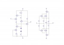
On the left, a JFET buffer designed by Arthur J. Metz in the '80s for Tek 'scopes (US Pat # 4,471,319) and modified to use N channel JFETs; on the right the input buffer of the Pioneer A09 Class A amplifier (authour unknown), modified to use available JFETs.
I plan to use LSK170 and LSJ74 JFETs for the input device(s) and J112 and J270 for the cascodes (the only reasonably complementary pair with an available P channel JFET amplifier - not switch - I've found; suggestions for alternative parts are welcome).
I'd like to hear expert opinions about the two topologies (beside the obvious disadvantage of the need for P channel JFETs for the Pioneer). Suggestions for alternative topologies are welcome but the complexity shall not exceed the Tek circuit and part selection shall not exceed the requirements of the Pioneer circuit.
Thank you.
Giorgio
I'd like to build a JFET buffer to be used either as an input buffer for a power amplifier or for S&K filters for electronic crossovers (similarly to the LX Mini crossover by Nelson Pass). I can't decide between two topologies.
On the left, a JFET buffer designed by Arthur J. Metz in the '80s for Tek 'scopes (US Pat # 4,471,319) and modified to use N channel JFETs; on the right the input buffer of the Pioneer A09 Class A amplifier (authour unknown), modified to use available JFETs.
I plan to use LSK170 and LSJ74 JFETs for the input device(s) and J112 and J270 for the cascodes (the only reasonably complementary pair with an available P channel JFET amplifier - not switch - I've found; suggestions for alternative parts are welcome).
I'd like to hear expert opinions about the two topologies (beside the obvious disadvantage of the need for P channel JFETs for the Pioneer). Suggestions for alternative topologies are welcome but the complexity shall not exceed the Tek circuit and part selection shall not exceed the requirements of the Pioneer circuit.
Thank you.
Giorgio
Attachments
Both circuits put an emphasis on low input capacitance, thanks to the boostrapping of the input FET's drain.
The TEK circuit keeps the FET in quasi-stasis, thanks to the cascoded source sink and the additional buffer transistor, meaning the final load will have little effect on the characteristics, unlike the Pioneer one.
It is probably possible to simplify and improve it at the same time by including it in a Taylor/White style scheme.
It would spare one or two FETs whilst improving the stasis-derived performance
Hi Elvee,
Thank you for your response. Yes, I consider cascoding the input JFET a valuable feature so that the circuit can be tolerant of sources with high impedance, as it might be the case in a crossover application.
Drive capability is taken care of by the output emitter follower in the Tek circuit and by push pull in the Pioneer. In both cases it cannot be pushed too much, the PNPs of the Tek circuit shall be duals with one BJT configured as a diode for best DC offset cancellation while increasing drive capability of the Pioneer circuit requires more (expensive) paralleled JFETs. Neither circuit is really suitable as a (high current) line driver, probably.
I'm not familiar with the Taylor configuration (WRT buffers, isn't it a current source? will look into it) but the White cathode follower (re-patented by Kikusui with JFETs!) is included in the Tek circuit by means of the second PNP BJT (it was designed with ICs in mind so no big caps, please) with some advantages, at the expense of simplicity, perhaps. So, I agree about sparing one BJT (and rather keep the JFET cascodes?) but feedback will remain and simplicity is still not the hallmark of this circuit. Pioneer is not better either as feedback is gone but some serious selection of active devices is still needed.
Not really, if CR1 is a perfect current source, it will prevent any feedback to the lower transistorsbut the White cathode follower (re-patented by Kikusui with JFETs!) is included in the Tek circuit by means of the second PNP BJT
Hi Elvee,
Thank you for your response. Yes, I consider cascoding the input JFET a valuable feature so that the circuit can be tolerant of sources with high impedance, as it might be the case in a crossover application.
I think you will find that crossover filters have a low impedance to the gate at high frequencies because of the filter capacitors, so gate capacitance is not an issue.
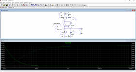
Here is what I mean: it is just an inelegant and clumsy attempt only meant as an example, and to make it work (sort of), it includes a cheat: capacitor C1.It is probably possible to simplify and improve it at the same time by including it in a Taylor/White style scheme.
It would spare one or two FETs whilst improving the stasis-derived performance
It could be refined, redesigned to achieve better performances without capacitors, but in its rudimentary form, it already reaches an output impedance of 5.4ohm, one order of magnitude or two better than a plain-vanilla source follower (it would be 1/Gm).
The linearity performance should be improved in the same proportion.
Since the bootstrapping transistor Q2 doubles as a Taylor engine, the transistor count is 4, of which only one is a FET
Attachments
Thank you everyone for chiming in. I will need some time to elaborate all the information.
Elvee,
Now I see what you mean with Taylor/White scheme. Thank you for taking the time to draw the schematic and run the sim. One reason that got me interested in the Tek buffer is PSRR (and no P channels, otherwise the Pioneer is just fine). One application I have in mind is as input buffer for an ICEpower class D amplifier where the supply rails are taken from the switching circuit. The White follower is probably not the best performer in this department but your circuit seems to be better.
Nelson,
I guess you are right (well, you are proven right by your LX Mini design 😉) but I'd like to select a buffer design to be as flexible as possible, so that I can re-use it in several applications without too many changes.
Regards
Giorgio
- Home
- Amplifiers
- Solid State
- JFET Buffers - Tektronix vs Pioneer