What are your thoughts for the attached plan?
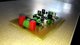
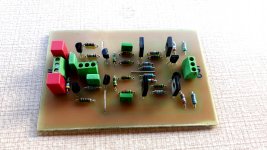
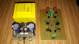
I drew a simple pcb for testing purposes. I plan to do live tests soon.
I drew a simple pcb for testing purposes. I plan to do live tests soon.
Attachments
Last edited:
If you want to avoid unity gain feedback stability issues, you might try the kulish corrector for the output: https://www.diyaudio.com/forums/solid-state/74861-single-darlington-line-preamp-3.html#post856982
A general remark: using HV transistors like the MJE's when they aren't actually needed is counter-productive.
Everything else being equal, this type of transistor is slower, has larger capacitances, lower gain, higher parasitic resistances, etc.
They are lots of low-voltage alternatives in a similar case
Everything else being equal, this type of transistor is slower, has larger capacitances, lower gain, higher parasitic resistances, etc.
They are lots of low-voltage alternatives in a similar case
indeed , as it hints to low noise, bc327-40, 337-40 might be a better choice for MJE pair transistors.
Fairchild or ON bd 140-139 have the highest hFE but not good enough...bC 327/337-40 should be much better although i'd go also with 2sc2240/2sa970 pr 2sc1815-2sa1015 as they are ow noise too, have enough current and high hFE.
I have a lot of varieties in stock.
I have a chance to try different combinations.
Meanwhile, Hamit Boztaş's own comments are as follows.
I have a chance to try different combinations.
Meanwhile, Hamit Boztaş's own comments are as follows.
This is a circuit that I have no doubt that every builder will be happy.
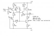
The circuit was already tested as a square wave and sine between 0-400KHz
300V/Us is also under the details
quite successful.
Differences in some frequencies, sometimes the ampl we use. sometimes it can be under loud speakers.
For the view from 0dB 7Hz-1MHz, the difference here may also be similar
I have no doubt about it.
While 100k input resistor should use 1u, the lower limit can be 5-7Hz 0 dB
For the 2.2u with the same input resistance resistance, this default could be 3-5Hz 0dB.
This can also be the cause of different reactions at lower frequencies.
For soft bass, input resistance can be used at 100K to 0.47U, 47K 1u.
For hard bass, 100K 1u-2.2u, 47K 2.2u-3.3u can be used.
The only adjustment input capacitor for your bass-bass preference.
It can be 100K-47K.
- Home
- Source & Line
- Analog Line Level
- Jfet Buffer